
Paxman Heavy-Fuel-Oil Engines
Types VF, VH, VK and VN - Introduced 1927
Notes:
a) Explanations of some terms used in diesel engineering can be found on the page A Glossary of Diesel Terms. Where appropriate there are links in the text below to the relevant entry on that page.
b) Where the term Diesel appears with a capital 'D' on this page, it refers to engines which at the time were protected by Dr Rudolph Diesel's patents. Where diesel appears with a lower case 'd', it is used as the now commonly accepted generic term for a compression-ignition engine.
Background Introduction
Although Paxman has been best known since the late 1930s for designing and building diesel engines, it entered the field comparatively late. The Company did not introduce its first compression-ignition oil engine to the market until 1927, some thirty five years after Richard Hornsby & Sons of Grantham started manufacturing oil engines in 1892.
Engineers continue to debate, with strongly held views on each side, who should be credited with inventing the oil engine. Dr Rudolph Diesel (1858-1913) is generally considered to be the inventor. However, it was an Englishman, Herbert Akroyd-Stuart (1864-1927), who first described two fundamental features of the modern diesel engine. It is true that Akroyd-Stuart's patents arose out of his work on overcoming the problem of pre-ignition and that his engine was a low compression semi-diesel or hot bulb type, requiring the application of heat to its vaporising chamber until the engine reached normal operating temperature. Nevertheless it was his patent (No 7164) of 1890 which described the principles of compressing the charge air in the cylinder before the introduction of fuel, and timed injection of a liquid fuel by means of a pump (i.e. solid injection). Diesel's patent (No 7241) was registered two years later and the engine it described relied on the heat generated during compression to ignite a fuel of coal dust introduced into the combustion chamber using compressed air (air-blast injection). Furthermore, Akroyd's patent was based on practical development work he had done. The year after the patent was registered, working examples of his engine were on public display and Akroyd-Stuart had made such progress that he was ready to enter into an agreement with Hornsby, granting them sole manufacturing rights. Commercial production commenced the year after that, the first engine being sold on 8th July 1892. The Hornsby-Akroyd became so successful that 32,417 were built. By contrast, the principles set out in Diesel's patent were based solely on theoretical work. After the patent was registered it took another five years or so to overcome substantial practical problems and develop an engine operating on Diesel's principles which could be put into production. Akroyd-Stuart, despite his pioneering work, remains virtually unknown to the general public whereas Diesel's name is universally recognised and has become synonymous with the oil engine.
In September 1903 Paxman announced its intention to commence manufacture of gas and oil engines in an advertisement for "a sound practical Engineer, thoroughly conversant with engines of this type". William Judd was appointed and he, in turn, recruited a Dutch engineer, Mr Palleman, to assist him. It is thought the Company produced its first gas engine in 1904 but there is evidence to suggest that it took another two or three years to overcome problems in developing an oil engine. The first Paxman oil engines were spark-ignition, running on light spirits such as benzine. Unfortunately the pre-1911 order records for these engines have been lost so we have no evidence of when production actually commenced. As events turned out it was the gas engine versions of this type which were more successful commercially and they remained in production until the late 1920s. More about the Company's early spark-ignition oil engines can be found on the Benzine Engines page.
In 1903 James Paxman expressed interest in manufacturing Diesel's engines under licence, if suitable terms could be agreed, for the Diesel Engine Company Ltd, which held the sales rights throughout the British Empire. Discussions with the licensees came to nothing. Nine years later, the Essex County Standard of 2nd March 1912 carried an announcement that the Diesel Engine Company Ltd, Carels Frères (who manufactured Diesel's engines in Belgium) and Davey Paxman & Co were about to amalgamate. For some unknown reason the amalgamation plans unravelled very shortly afterwards. Consolidated Diesel Engine Manufacturers Ltd was incorporated on 27th March 1912 but without Paxman being a part of the new business or having a stake in it. CDEM went on to build a large new factory at Hadleigh Road, Ipswich which was completed the following summer. The location may have been influenced by its proximity to Reavells, who could supply compressors for the engines' air blast fuel injection. Perhaps it was Paxman's abortive attempts over a period of ten years to secure an involvement in Diesel engine manufacture, and the growing threat of the oil engine to its steam engine business, which explains the sense of urgency behind the Company's moves in 1913 to develop a compression-ignition engine of its own.
In the Paxman copy order books there is an entry under Order No 12436, dated 3rd October 1913, for a 'Crude Oil Engine' No 18466 for Davey Paxman & Co, Colchester. The microfilm record of the entry in the original order book has an order date of 2nd October 1913 and a note saying "to be completed by earliest". The order was for a 10¾" bore x 16" stroke gas engine to be converted to a 22 bhp crude oil engine "for urgent completion". Alex Walford has seen a photograph of this first Paxman experimental compression-ignition engine and says it bears a very close resemblance to the Akroyd-Stuart design on which the patents had by now expired. Attractions of developing such an engine would have included a well proven and accepted technology, the availability of designs which were no longer protected by patent, and the substantial time and cost savings accruing from being able to base a new engine on the Company's existing range of gas engines. It is possible, if not probable, that plans for the future of this engine were thrown off course by the unexpected death of Paxman's oil and gas engine expert, William Judd, in November 1913. In any event work on developing an oil engine came to a halt with the outbreak of World War I when the Company became fully occupied with war production.
There is no evidence of Paxman undertaking any significant development of an oil engine in the years immediately following the end of the War. Admittedly the first year or two were particularly difficult. During the War valuable overseas markets had been lost and now the Company faced greatly increased costs for major expenditure items such as materials, fuel and wages. To add to the problems many pre-War patterns had become obsolete and were in need of replacement. With such concerns on their minds it is understandable if the Directors did not view oil engine development as a priority.
In his book Steam and the Road to Glory, Andrew Phillips makes reference to Charles Barnes, Paxman's new Chief Draughtsman at the time, who he says may well have been the Charles Barnes who designed the first oil engine at Ruston and Proctor. He adds that Ruston's merger (in September 1918) with Hornsby, a firm with the largest fund of oil engine experience in Britain, cannot have enhanced Barnes's career prospects there and that a move to Paxman, who were desperate to develop semi-diesel engines, would have been wholly suitable to both parties. Andrew Phillips goes on to explain that Barnes attended the Royal Agricultural Society's show at Cardiff in 1919, a show dominated by gas and oil engines among others, and submitted a report about it to James Paxman. It is noteworthy that the latter's four page reply to Barnes contained no reference to oil engines but was devoted solely to the design of a new generation of portable steam engines. (1)
If this Charles Barnes was the man who had designed oil engines at Ruston, the only hint of him playing a part in the design or development of oil engines at Paxman is a comment made by an old ex-Paxman employee to Andrew Phillips some years ago. Very little progress, if any, appears to have been made on this front until 1925. Possibly that was a consequence of Paxman becoming a member of the Agricultural & General Engineers (AGE) combine in late 1920. AGE's policy was to discourage competition or product overlap between member companies, one of which was Blackstone & Co of Stamford, a leading maker of oil engines. If AGE did inhibit Paxman's post-War efforts to develop an oil engine, to protect Blackstone's interests, it is somewhat ironic that Paxman's first successful compression-ignition engine owed a great deal to Blackstone and its expertise in this field.
At last, in 1925, we see Paxman fully committed to developing a compression-ignition oil engine and making substantial progress. Work started on building prototypes which were to undergo two years of extensive tests and trials before the engine was publicly launched (2). This time the Company opted for a vertical type, not the more conventional and common horizontal. The design incorporated Blackstone's recently introduced spring injection device as well as other features of the Stamford company's well-respected horizontal engines. The explanation for this is to be found in two important Paxman-Blackstone connections. One was Edward Paxman, youngest son of Paxman's founder, and the other AGE, of which both companies were members.
Edward Paxman had graduated from Cambridge with 1st Class Honours in Mechanical Engineering in 1923. He then spent probably about a year at Metropolitan-Vickers Electrical Co in Manchester before going on to Blackstone to receive further practical engineering and industrial training. Blackstone was a major manufacturer of oil engines and it seems reasonable to assume it was his experience here which fired Edward Paxman's enthusiasm for the diesel. Of more immediate relevance is the fact he would have been at Stamford at the time spring injection was being introduced and hailed as a major advance in fuel injection technology. He must surely have discussed with his contacts in the family firm at Colchester what he was learning about oil engines, and particularly this latest innovation, at Blackstone. It is impossible to imagine that Edward Paxman was not a key catalyst in triggering the oil engine activity seen at Standard Works in 1925 even though he himself did not join the staff there until the following year.
Blackstone launched its spring injection device in 1924 and went on to incorporate it in all its engines. Spring-injection was a major advance on air-blast fuel injection which up to that time was the method usually employed with larger oil engines. Some details of the system are given in a later section of this page and its operation is explained on the page Blackstone & Carter's Spring Injection. What initially seems surprising is that Paxman was allowed to use Blackstone's invention, under licence, just a year or so after it first appeared on Stamford's own engines. Why was Blackstone apparently willing to surrender the competitive advantage of such a valuable innovation by allowing a potential competitor to use it and to use it so soon? As previously mentioned, both companies were members of AGE. Marketing policy and competition issues were decided centrally by AGE rather than locally by individual member companies. AGE policy was that member companies should co-operate but keep to their own distinct product lines and markets to avoid competing against each other. Blackstone's engines were of the horizontal type whereas Paxman was developing the vertical type. With each aimed at different markets, allowing Paxman to use Blackstone's spring-injection in vertical engines would be consistent with AGE's overall business strategy and avoid Paxman encroaching on Blackstone's horizontal engine market.
Without more evidence we can only speculate on Paxman's principal reasons for deciding to build the vertical type of engine. Of Paxman's pressing need to develop a range of oil engines, as the decline of its steam engine sales accelerated, there can be no doubt. Taking advantage of Blackstone's state of the art fuel injection technology, but in a way that did not place the two companies in too much competition with each other, must have looked an attractive solution. What is less obvious is the extent to which Paxman was conscious of, and motivated by, the potential advantages of the vertical over the horizontal for certain markets and had identified the potential of the marine market. Certainly the marine market was in its sights by the time the new verticals were introduced in 1927. One of Paxman's first catalogues for this type of engine is entitled 'Marine Oil Engines' (publication No 931, dated 1927). It is also pertinent to note that during the launch year Paxman chose to exhibit its new engines not only at the British Industries Fair and the Royal Show, but also at the Shipping, Engineering and Machinery Exhibition. However it was not the marine market in which Paxman had its greatest early successes.
Tom McIlraith
Another possible indicator of Paxman's interest in the marine market lies in the man who was probably recruited specially to design the new engine or at least do the engineering drawings for it. Alex Walford has seen many of the drawings and noticed that nearly all of them carry the initials "TM". Tom McIlraith joined the company in 1925 and is thought to have come from William Beardmore & Co of Glasgow. Beardmore was a large Clydeside engineering and shipbuilding concern whose business interests included the design and manufacture of diesel engines. It is interesting to note that during the early 1920s the company was doing some innovative work on the Beardmore-Tosi marine diesel engine (3). Beardmore hit hard times in the 1920s, forcing it to retrench, which could explain McIlraith's willingness to move to Colchester to pursue his career. No doubt the prospect of designing a completely new engine would in any case have been highly attractive to a man with his background.
A book of mathematical tables found at Paxman has inscribed inside "T McIlraith, 11 Lansdale Street, Peel Green. October 27, 1911". Peel Green is within a mile of Patricroft in Manchester, home of the former Gardner diesel business which is possibly where McIlraith worked during the early part of his career. Alternatively he may have worked for one of the other engine manufacturers in this part of Manchester: Browett Lindley & Co, also of Patricroft, or W H Bailey who made hot air engines. During his later career at Paxman he was not only responsible for the heavy-fuel-oil engine's drawings but was also a patentee, with Paxman, of the engine's 'Silent Valve' (4). The design and origins of this valve are explained in a later section of this page. Tom McIlraith retired in 1947 after 22 years service with the Company (5).
Rapid Progress under Edward Paxman
Paxman's move into compression-ignition engines had been long delayed but what is striking is the number of innovations and speed of development after its first oil engine appeared on the market in 1927. The design of Paxman engines evolved rapidly, with increasing speeds and power outputs, which opened the way to an expanding range of applications. Much, if not most, of the credit for this must go to Edward Paxman who joined the business in 1926 and was appointed shortly after as Chief Engineer. It was his enthusiasm for developing the diesel, his technical understanding, foresight, leadership and energy which led to the Company becoming an acknowledged leader in diesel engine design and manufacture. What his father had achieved in developing and promoting efficient high quality steam engines, Edward Paxman achieved in the field of diesel engineering despite a life tragically cut short in 1949 at the age of only 47.
Development Prototypes - 1925
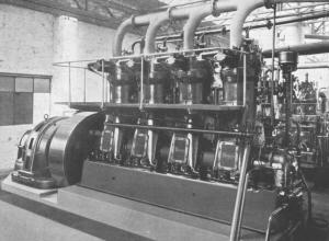
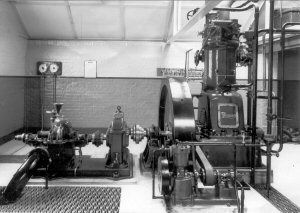
 The first development prototype is believed to have been a single cylinder engine, 10" bore x 15¼" stroke, built in 1925. With a rating of 40 bhp at 330 rpm in its single cylinder form, engines of this cylinder size became the Type VH. The single cylinder prototype was followed by a three cylinder development engine. The photograph here shows that engine in the power house at Standard Ironworks where it was installed for test and experimental purposes. As the first multi-cylinder type exhibited by Paxman was a 3VH, the likelihood is that this three cylinder development engine was a Type VH, having the same bore and stroke as the single cylinder prototype. The prefix 'V' used in the designations of the new engines stood for 'vertical', not to be confused with 'Vee' form which later emerged as the engine type generally associated with Paxman.
Paxman's Cold Starting Heavy-Fuel-Oil Engine is Launched - 1927
The first order for the new engines was entered in the books on 22nd December 1926. It was for two single cylinder oil engines for exhibition at the British Industries Fair in Birmingham the following February. One was a 40 bhp VH, as described above. The second was a Type VK, 12" bore x 17" stroke, with a rating of 60 bhp at 300 rpm. It was at the 1927 BIF that Paxman's new vertical Heavy-Fuel-Oil Engines were first shown to the public. The Types VH and VK, including their later VHE and VKE variants, were to become two of the three most popular engines in the range.
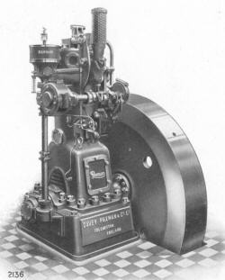 During the launch year the Company also exhibited its new engines at the Royal Show at Newport in July and at the Shipping, Engineering and Machinery Exhibition held at Olympia in September. At these two events Paxman introduced a further type, the smaller VF, having an 8½" bore x 12" stroke and producing 25 bhp per cylinder at 360 pm. On display, alongside the single cylinder VF, was a three cylinder Type VH rated at 120 bhp.
Single cylinder Type VF.
Bearing in mind the engine had only just been put on the market, and that Paxman had no previous experience or reputation as a compression-ignition oil engine builder, a commendable number of sales were achieved during 1927. The first engine went to a local and long-standing Paxman customer, Severalls Hospital in Colchester. The order for the two cylinder 80 bhp Type VH was placed on 30th April 1927 and left the factory on 17th June. Once installed at Severalls it became a showpiece. Prospective customers visiting Colchester were taken to see it running in the Hospital's power house.
It was also a local customer who placed the first order for a two cylinder Type VK. Bought by E Chopping & Sons, the engine was installed in their flour mill at Fingringhoe, just south of Colchester. A picture of it in situ appears in catalogues 952 and 987.
On 30th June the Anglo Oriental & General Investment Trust Ltd placed an order for no less than nine engines, destined for three Cornish tin mines. Two of the engines were 3VHs and the remainder were VKs, ranging from 3 to 6 cylinder versions. Tin mining in Cornwall became uneconomic shortly after and most of the engines were then sold on to other businesses.
In September 1927 Armagh Urban District Council, Northern Ireland ordered a 4VH and a 2VH. It was the first of a stream of local authority orders for engines for electrical power generation. This important, if somewhat short-lived, market for Paxman provided valuable references for the Company as it sought to enter other markets.
Catalogues - 1927 and 1928.
Two catalogues for the new engine range were issued in 1927. No 931 is entitled 'Marine Oil Engines for Auxiliary Work, Lighting Sets, Etc.' which is evidence of Paxman's interest in the marine market. No 932 has the title 'Heavy-Fuel-Oil Engines' and was prepared in September. The types and sizes of engines offered in each catalogue are identical and as shown in the table below. Cylinder dimensions are not given in the catalogues; those shown below are taken from a data sheet found in Paxman's Service Department.
| Type | Number of Cylinders | BHP per cylinder | Speed (RPM) | Bore & Stroke | |
|---|---|---|---|---|---|
| Normal Load | Max Overload for 1 hr | ||||
| VF | 1, 2, 3, 4 | 25 | 29 | 360 | 8½" x 12" |
| VH | 1, 2, 3, 4, 5, 6 | 40 | 46 | 330 | 10" x 15¼" |
| VK | 1, 2, 3, 4, 5, 6 | 60 | 69 | 300 | 12" x 17" |
| VM | 3, 4, 5, 6 | 85 | 97.7 | 280 | |
| VN | 3, 4, 5, 6 | 105 | 120.7 | 270 | 15½" x 20" |
| VP | 3, 4, 5, 6 | 125 | 143.7 | 260 | (15.7/8" x 20" ?) |
| VR | 3, 4, 5, 6 | 150 | 172.5 | 250 | |
The best selling engines in the range were the VF, VH and VK and their later enclosed versions. Only eleven VNs were built, counting the VNE and VNS variants. The only VP to be made was an 8 cylinder 'enclosed' VPE type, despatched to Australia in April 1932. There is no record of any Type VM or VR being built.
At the back of catalogue 932 four pages (pp. 29-32) are devoted to 'Paxman Horizontal Cold Starting Heavy-Fuel-Oil Engines'. Two illustrations show what are obviously 'badge engineered' Blackstone spring injection horizontals. The Blackstone name on each engine has been obliterated and overlaid with the Davey Paxman name and logo. (Paxman did not build any of this type, but did sell some Blackstone ones.) Virtually identical to Paxman catalogue 932, in text, layout and illustrations, is Blackstone catalogue 947, produced in June 1928, entitled 'Blackstone "Spring Injection" Cold Starting Vertical Oil Engines'. The engines described and pictured in the Blackstone catalogue are in fact Paxman verticals. Even photographs of engine test bays are of the test facilities at Paxman's Colchester Works although the captions are naturally silent on this point. Again pictures of engines have been 'doctored', this time by obliterating the Paxman name, for example on bedplates and crankcase doors, and overlaying it with the Blackstone name.
It would appear that during the latter half of 1928 there must have been a change in AGE's marketing strategy and a decision to drop the practice of badge engineering. Page 40 of Paxman's Heavy-Fuel-Oil Engine catalogue No 952, prepared in December 1928, is headed "Horizontal Cold Starting Heavy-Fuel-Oil Engines". The first paragraph starts "Where the horizontal type of cold starting Oil Engine is preferred we refer clients to our Associated Firm – Messrs Blackstone & Co Ltd, of Stamford – … "
By the time of Paxman's catalogue 952, December 1928, the Types VM and VP are no longer listed. Possibly it had been decided that now their power ranges were covered adequately by the VK, VN and VR. The VN's speed had been increased from 270 to 300 rpm (the same as the VK) with a corresponding increase in power output to 116.6/135 bhp per cylinder. Catalogue 952 offers an 8VN and 8VR, and states "Engines built in all sizes from 1-8 cylinders". The potential of the power generation market is recognised in notes that "The VF sizes can be run at 375 rpm for synchronous speeds for direct coupling to Alternator, 50 cycles and up to 400 rpm for D.C. The VH sizes can be run at 333 rpm for synchronous speeds for direct coupling to Alternator, 50 cycles and up to 350 rpm for D.C. The VK sizes can be run up to 315 rpm if desired". At the increased speeds the engines developed increased powers in direct proportion.
VN Engines for Rosyth and Ashford - 1928
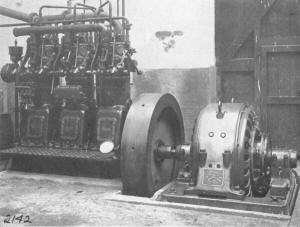
 The first two VNs to be built, both of which are shown in catalogue 952 (pp. 14, 2), were despatched from the factory in 1928. No 22786, a 4 cylinder VN, left the Colchester Works in May and is pictured here installed at H M Dockyard, Rosyth.
The second more significant order, placed in March that year, was for an eight cylinder engine (No 22885) delivered to Ashford (Kent) Urban District Council Power Station in September. Having a rating of 900-1070 bhp, and driving a 600 kW alternator, it was at the time the largest airless injection diesel engine at work in Great Britain. This achievement was referred to by Edward Paxman in his speech at the retirement dinner held for Tom Ilraith and two other of the Company's oil engine pioneers, in October 1947, when he said "within three or four years of starting (to make oil engines) we built the largest engine in the country" (5).
Turbocharging Introduced - 1929
The next stage in Paxman's development of its heavy-fuel-oil engine was the introduction of a turbocharged version of the Type VN in 1929. This was designated the VNS, the 'S' suffix standing for 'supercharged'.
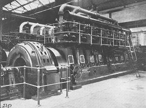 In February an order was received for an eight cylinder VNS for Basingstoke Corporation Electricity Works. The engine, No 23192, was installed during September 1929 and claimed to be the first Büchi turbocharged diesel to be put to work commercially on any land installation in the British Isles. In March Ashford U D C, which had taken delivery of a naturally aspirated 8VN the previous year, also ordered an 8VNS. This second engine, No 23210, had an 800 kW rating and was sent to Ashford on 10th October. The 8VNS engines which entered service at Basingstoke and Ashford in 1929 were the two largest airless injection pressure-charged engines in ordinary commercial use in Britain at the time.
8VNS installed at Ashford, Kent
Paxman records suggest these two engines were similar but not identical. The Basingstoke engine had a Witton alternator and the Ashford engine an English Electric alternator. The contracts included erection at site and reveal that there were differences in the foundations for each set.
The turbochargers were supplied by British Brown Boveri. An interesting feature of the engines was the fitting of adjustable cam followers so that the valve timing could be altered to allow reversion from turbocharging to natural aspiration if required.
The ratings quoted in the contracts for these 8VNS engines were 1,160 bhp (865 KWb) at 300 rpm for 12 hours continuous, 1,276 bhp for 2 hours and 1,450 bhp maximum. The naturally-aspirated 8VN supplied to Ashford in 1928 was rated at 900 bhp for 12 hours continuous, from which it can be calculated that turbocharging increased the power output by nearly 30%.
A number of teething problems were experienced with these early turbocharged engines, such as the lubrication and cooling of the bearing between the rotor of the exhaust gas turbine and the blower, cylinder head cracking, and burning of the turbulence block cast on the piston top, but these difficulties were overcome. For both types of engine fuel consumption was about 0.59 lbs per kW hour. Interesting to reflect that, over seventy years later, many turbocharger failures continue to be attributable to problems with the lubrication and cooling of the bearings regardless of turbocharger make or engine type!
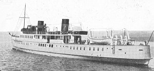 Only two other VNS engines were made, Nos 23679 and 23680, a pair of five cylinder types, each rated 800 bhp (597 KWb) continuous, 880 bhp for 2 hours. They were installed in 'DEV Lochfyne' which entered service with David MacBrayne in 1931. That in itself was a landmark as Lochfyne was the first passenger ship with diesel-electric propulsion to operate in British coastal waters. It marked an important step and success in Paxman's attempts to establish itself in the marine propulsion diesel market. Two subsequent MacBrayne vessels fitted with later types of Paxman engines for main propulsion were 'Lochnevis' (1934) and 'Lochiel' (1939). More details of the engines installed in Lochfyne and Lochnevis can be found on the page Diesel-Electric Marine Propulsion.
DEV Lochfyne - diesel-electric propulsion with two 5VNS engines.
Like the two earlier VNS engines, those for Lochfyne had turbochargers supplied by British Brown Boveri. There is a note on the contract files that specific care must be taken during engine build to ensure that the exhaust manifold system was free from debris, as problems had been experienced on two previous contracts with such debris being blown into the turbine and damaging it.
'Enclosed Type - Forced Lubricated' - 1929
The introduction of turbocharging on the Type VN engines was not the only major innovation in 1929. Of equal if not greater significance in the history of the development of Paxman's oil engines was the arrival of the 'Enclosed Type - Forced Lubricated'. This step marked an important improvement in the design of the existing standard (industrial, non-marine) range of heavy-fuel-oil engines and heavily influenced the design of the next generation of Paxman engines, the Heavy Duty Diesel.
The Company's early heavy-fuel-oil engines were open types. The camshaft and valve operating gear were not enclosed. Nor were crankcases or the spaces between them fully enclosed. A 1927 catalogue even makes a virtue of this, saying 'cool running is assured by the efficient ventilation of the crankcase, the sides of each cylinder casting being open with louvered covers'. With the lubrication systems employed there was little need to enclose these engines for industrial applications unless operating conditions were abnormally dusty or damp. Crankshaft and camshaft bearings were lubricated by ring oilers. Lubrication of cylinders and connecting-rod bearings, both big and small ends, was by means of a mechanical force feed lubricator (i.e. forced drip-feed). The two 1927 catalogues mention that main bearings of the marine types were forced lubricated, but the text clearly implies this was only by a mechanical force feed lubricator.
 By the time of the December 1928 catalogue (952), engines for marine purposes are arranged "fully enclosed" with forced lubrication fitted throughout. Forced lubrication for these is now performed by a pump circulating oil through the main bearings and via the crankshaft to the large and small end bearings. It was this system of forced flow lubrication of main, big end and small end bearings which was introduced during the latter half of 1929 as an option across the standard heavy-fuel-oil engine range. Enclosure of crankcases now became necessary to contain lubricating oil thrown off bearings as it flowed through them under pressure. However enclosure was restricted to crankcases, the spaces between them immediately above the crankshaft and the chain drive from the crankshaft to the camshaft. The latter was introduced as an alternative to the original vertical drive shaft with a skew gear at each end. On 'Enclosed Type - Forced Lubricated' engines the camshaft itself remained open and camshaft bearings were still ring oiled. Whether camshafts were enclosed or lubricated differently on the 'fully enclosed' marine versions is unclear from the catalogues which unfortunately contain no illustrations of them.
Two cylinder Enclosed Type with chain-driven camshaft.
Enclosed types of the heavy-fuel-oil engine range were designated VFE, VHE, VKE and VNE. The first of these was despatched in late 1929 and a good number of orders for them was received during 1930. The new arrangement made for much improved lubrication of the main and connecting rod bearings, cooler running and longer bearing life. It became possible to run engines for longer periods unattended and to increase running speeds with a proportional increase in power output. An old Company data sheet prepared for internal use suggests that these enclosed engines had the same speeds and outputs as their earlier open type counterparts. However, in catalogue 987, published around 1931, the speeds and power outputs of the VFE, VHE, and VKE are higher than their respective open versions. Those for the VNE remain the same as for the uprated VN. By the time of this catalogue only enclosed types are offered and the quoted outputs and speeds are summarised in the tables below. Outputs and speeds of their open type predecessors are shown in brackets for ease of comparison.
| Type | Number of Cylinders | BHP per cylinder | Speed (RPM) | |
|---|---|---|---|---|
| Normal Load | Max Overload for 1 hr | |||
| VFE | 1, 2, 3, 4, 5, 6 | 35 (25) | 38 (29) | 500 (360) |
| VHE | 1, 2, 3, 4, 5, 6 | 48 (40) | 53 (46) | 400 (330) |
| VKE | 1, 2, 3, 4, 5, 6 | 70 (60) | 77 (69) | 350 (300) |
| VNE | 3, 4, 5, 6, 7, 8, 9, 10 | 116.6 (116.6) | 128.3 (135) | 300 (300) |
| Supercharged (turbocharged) VN - Type VNS (note output is in kW, not BHP.) | ||||
|---|---|---|---|---|
| Type | Number of Cylinders | kW per cylinder | Speed (RPM) | |
| Continuous Rating | Max Overload for 1 hr | |||
| VNS | 5 | 100 | 110 | 330 |
| VNS | 6, 7, 8, 9, 10 | 100 | 110 | 300 |
In an old notebook there is an entry headed 'Increased cylinders'. This has the following: VFE 9" x 12", VHE 10½" x 15¼", VKE 12.5/8" x 17", VPE 16" x 20". There is nothing to indicate whether the increased bore sizes were standard for Enclosed types or were only for special orders. The stroke sizes are the same for the equivalent type of Open engine.
Applications and Markets
In its publicity literature Paxman pointed to a number of advantages that the oil engine had over the steam engine for many applications. It had a lower initial cost, required less space, could be started instantly, and be left running unattended for long periods. Although the oil engine was unquestionably the way forward for Paxman we should not assume that everyone in the Company shared Ted Paxman's enthusiasm for it. Much of the Company's reputation had been built on producing high quality steam engines and these were still being made at Colchester; the last did not leave the factory until 1934.
Applications for which Paxman supplied its heavy-fuel-oil verticals were generally those where steam engines would previously have been used as prime movers. Typical examples were driving factories and mills, driving compressors (mainly refrigeration), powering laundries and dairies, and standby and emergency power generation. The most important market for Paxman at this stage was local authority power generation. During the 1920s many municipal authorities, both in the UK and overseas, began to install diesel prime movers for base load power generation in their power stations or 'Electricity Works' as they were often called. This proved a fruitful, albeit relatively short-lived, source of business for Paxman. The local authority power generation market in the UK quickly disappeared with the growth of the National Grid and the construction of much larger power stations during the 1930s. A list of several local authority power generation customers forms appendix 1 at the bottom of the page. Another major market was also in the local authority sector, again both in the UK and overseas. Many engines were purchased by water boards and waterworks for pumping. A list of some of these customers forms appendix 2. Orders from local authorities and government bodies featured prominently in Paxman catalogues, being valuable references for establishing the Company's credibility as an oil engine manufacturer.
When the decision was made to develop a vertical, rather than horizontal, oil engine one of Paxman's key targets was the market for marine auxiliaries. Although a few were sold for on-board power generation, the largest proportion of the Company's heavy-fuel-oil engines were purchased for land-based installations. The biggest marine market coup was securing the engine order for Lockfyne's diesel-electric propulsion system, referred to earlier. This does not appear to have led to any substantial increase in the sales of marine versions of the heavy-fuel-oil engine itself. Its main significance was the raising of Paxman's profile and credibility in the market which did lead to sales of later engine types for marine applications.
Details of virtually all the heavy-fuel-oil engines sold, and their respective customers, can be found on the page Oil Engine Listing - 1920s & 1930s.
Additional Technical Details Of The Heavy-Fuel-Oil Engine
Advantages of the Four-Stroke Design
Although early compression-ignition engines were frequently built on the two-stroke principle, which has remained the usual choice for large marine main propulsion engines, all Paxman oil engines have been four-stroke designs. In the Heavy-Fuel-Oil Engine catalogues referred to earlier, the Company argued that the four-stroke engine was more economical to run, more reliable, and less costly to maintain. The largest cost in running any engine is fuel and the consumption of the four-stroke was about 20% less than the equivalent two-stroke for well-recognised reasons. In the four-stroke design, exhaust gases are thoroughly scavenged before the inlet stroke and a full charge of fresh air allows complete combustion of the fuel. Furthermore, following combustion the exhaust valve remains closed, the gases maintaining pressure on the piston until the maximum possible useful energy has been extracted.
The four-stroke used less lubricating oil and was cooler running. It was also more accessible to work on than the two-stroke with its boxed-in pressurised crankcase which involved longer down-times for repairs. Cylinder liners of the two-stroke suffered more rapid wear. The ports were liable to distortion because of the inflow of cold air on one side and the outflow of hot exhaust gases on the other. Other advantages claimed for the four-stroke were its perfect combustion and lower use of lubricating oil. One consequence was a clean exhaust making the engine suitable for use in applications where a smoky or dirty exhaust would be unacceptable. The virtual absence of carbon deposits in the engine itself resulted in long engine life and allowed it to be run for long periods with very little maintenance.
General Construction and Other Features
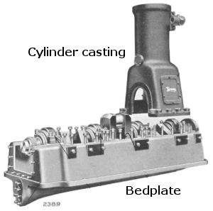 The Heavy-Fuel-Oil Engine had a substantial deep cast-iron bedplate which carried the main bearings. The crankshaft was secured to the bedplate by nuts holding down covers on top of each of the main bearings. By removing a cover both the top and bottom halves of a crankshaft bearing could be removed or replaced without disturbing other parts of the engine.
Between each main bearing was an individual cylinder casting or stand, the lower part of which was an 'A' frame supporting the cylinder itself. This housed a detachable cylinder liner, the lower end of which was free to expand and contract with changes in working temperature. The bottom part of each cylinder stand formed the crankcase for the relevant crank and had detachable covers to allow easy access to the big end bearing.
The cylinder head complete with inlet valve, exhaust valve and other fittings could be detached as a single unit by disconnecting the various pipes and removing the eight holding down nuts.
The feature of individual cylinder castings made it possible to vary the power output of, for example, a VH or VN by simply adding or removing one or more cylinders. All components could therefore be standard across the range for each engine type, apart from the bedplate, crankshaft and camshaft. Another benefit of this arrangement was that larger engines could be split down into more manageable units for transport and then erected relatively easily on site.
An important selling feature in the 1920s was the ability of these engines to start instantly from cold. They had a compression ratio of 13.4 : 1 and starting was by admission of compressed air into the cylinders. Many other oil engines needed pre-heating or coaxing with petrol or paraffin before starting or being able to run on their normal fuel. A further advantage of the new Paxman engines was that they could be started against partial or even half load which in some applications removed the need for a friction clutch.
The engines could be run on almost any grade of fuel as long as it could be pumped, including thick fuel which needed pre-heating. In the latter case a small adaptation could be made to the engine to use some of its heat for this purpose. Alternatively the engines could be converted at minimal cost to run on town, producer or natural gas. No change of the cylinder head or valve gear was necessary, the compression ratio being reduced by an alteration to the turbulence plate. Paxman Service Department records suggest that only five of these gas engine variants were sold; three 3VFEGs, a 2VHEG and a 5VHEG.
Blackstone & Carter's "Spring Injection" Device
In the mid to late 1920s most other manufacturers of large oil engines were using pneumatic or 'air blast' fuel injection. Fuel oil was injected into each cylinder with compressed air, at around 800 to 1,000 psi, from an air bottle or receiver. The air blast provided atomisation of the fuel and turbulence to ensure an even distribution of the air and fuel mixture. Maintaining a high pressure air supply required a compressor which typically absorbed about 5% of an engine's power output.
In 1924 Blackstone & Co Ltd of Stamford introduced their patented 'spring injection' device, a form of what is termed mechanical, solid, or airless injection, which was incorporated in their horizontal oil engines. Paxman obtained a licence to use this system on its new vertical heavy-fuel-oil engines. A metered quantity of fuel was delivered by a governed pump at about 10/15 psi to a chamber on the cylinder head, where it was totally confined and only subjected to pressure immediately prior to injection. Injection occurred at about 1,000 psi and produced a prolonged and almost perfect combustion. Benefits claimed for 'spring injection' included lower fuel consumption at all loads, a clean exhaust, and efficient functioning even at very low engine speeds. A more detailed explanation of its operation is given on the page Blackstone & Carter's Spring Injection.
Spring injection was developed by two brothers, Frank and Evershed (known as Tod) Carter who worked for Blackstone & Co at Stamford. Frank and Tod were responsible also for a number of other innovations in oil engine design and became respectively Works Manager and Chief Engineer at Blackstone.
The Paxman Patent Silent Quick Acting Valve
As argued in Paxman's catalogues for its heavy-fuel-oil engines, the efficiency of an internal combustion engine is heavily dependent on the design of its valves and valve gear, the exhaust valve being the more important. The objective is to retain pressure on the piston to the last fraction of a second, and then rapidly open the exhaust valve to avoid back pressure. The conventional approach in the early 1920s was to use a sharp cam to achieve rapid opening of the valve and a strong valve spring to ensure the roller on the cam follower followed the cam path. This arrangement resulted in the exhaust valve being jerked off its seat, held open for a time, and then brought back on its seat with great force. In consequence it was noisy, necessitated frequent grinding and adjustment of the valves, while the valve stem and guides also suffered rapid wear. Furthermore, the powerful spring made withdrawing the valve for grinding and replacing a troublesome business.
The Paxman Silent Valve, used for exhaust valves on the Company's heavy-fuel-oil engines, was based on the valve gear employed on Paxman-Lentz steam engines. That valve gear had proved very successful in practice and is described in the Paxman-Lentz section of the Steam Engineering page. Adapted for use on the new oil engine, the design was covered by Paxman and McIlraith patents (4). In place of the usual rotating cam and rocker arm, the valve gear used a rocking cam operated by an eccentric on the half time shaft. This cam operated on the Paxman-Lentz principle whereby the valve was freed gently from its seat, rapidly opened, held open for a short while, rapidly lowered again and then eased gently onto its seating in a smooth controlled manner. The arrangement avoided the noise and constant shocks associated with conventional exhaust valves and the accompanying wear, resulting in minimum wear to the valve and its seating and exceptionally long life. The absence of a powerful valve spring also made the task of removing and replacing valves much easier when any maintenance was required.
Surviving Examples
No 22795. This four cylinder Type VH would appear to be the oldest surviving example of a Paxman Heavy-Fuel-Oil engine. Ordered by Blackstone & Co, one of Paxman's sister AGE companies, for Clutterbuck Brothers of Melbourne, Australia, it was dispatched from the Colchester factory on 2nd March 1928, early in the year after Paxman launched this range of engines. An interesting feature of the engine is that it carries the Blackstone branding even though it was built by Paxman and has a Paxman number. For many years it was owned by the Timms family in Australia. In 2009 it was acquired by Stephen Hendrie who, by the end of that year, had managed to get the engine to his home city of Christchurch, New Zealand, where he plans to restore it to running order. Stephen requested a copy of the maintenance manual which is hard to come by as the engine is over 80 years old. Fortunately the Paxman Archive Trust has access to a manual for this early open-type of Paxman Heavy-Fuel-Oil engine, which we were able to copy for Stephen, and we look forward to hearing about progress on the restoration.
 No 23008. A single cylinder Type VK, now at the Museum of Power, at Langford, near Maldon, Essex. No 23008 was one of three single cylinder VKs ordered by the Metropolitan Water Board on 23rd July 1928 (two for Cheshunt, one for Hoe Lane Pumping Station, Enfield), and despatched on 11th March 1929.
Engine No 23008 as originally installed at Cheshunt.
The engine was brought to Langford from Kempton Park where it had suffered flood damage whilst in storage in a dismantled state. Fortunately the crankshaft and cylinder liner were in relatively good condition, having been well greased prior to storage. The smaller components were the worst affected but these, including the Spring Injector, were refurbished or replacements made where necessary.
Right: Single-cylinder VK, No 23008, at the Museum of Power, March 2025.
Photo © Dick Waylen 2025
The lengthy and major restoration was carried out by Alex Walford who had completed most of the work by August 2003. A decision then had to be made about where to site the engine in the museum before preparation of a concrete base with holding down studs and a pit to accommodate the flywheel. That work could not proceed until the necessary funding was available but by late July 2007 the engine was finally in place. It first ran again on 5th August 2008, 80 years after Paxman received the order for it.
No 23218. A single cylinder Type VH, ordered on 15th March 1929 for the Royal Technical College, Glasgow, and despatched on 11th November that year. It remained there, in what became the Mechanical Engineering Department of the University of Strathclyde, until comparatively recently and was used for experimental work by students on thermodynamics courses. Mr Steve Green of Norfolk acquired the engine from the University in May 2010. Steve tells me the engine is absolutely like brand new and that he has never come across such an engine in this condition. It came with a large box of new spare parts including piston, liner, injector, full sets of main and big end bearings and numerous bits - all that one would need to keep the engine running for a lifetime. Although the order book entry shows it as an open type VH engine, photographs of the engine reveal it to be an 'Enclosed Type - Forced Lubricated' VHE.
No 23407. The largest known surviving Paxman heavy-fuel-oil engines still in working order. This 6 cylinder Type VN was ordered on 19th October 1929 and dispatched from Colchester on 20th February 1930. It was sold to Marlborough Power Station, Blenheim, New Zealand (South Island) where it remains, now in preservation. Open days at the old power station are held two or three times a year when members of the public can see the engine running. As far as we know it is the only 6 cylinder version of a VN ever built. The history and further details of this engine appear on the page Paxman 6VN Engine - No 23407.
No 23673. A single cylinder Type VH engine, originally sold to Cocksedge Ironworks of Ipswich for one of their customers, H Dean of Needham. It was despatched from the works on 13th December 1930 and powered machinery at Harry Dean's quarry at Weybread, near Needham, on the Suffolk/Norfolk border. The engine was withdrawn from service, probably in the early 1970s, and then left in storage for about thirty years. No 23673 was sold at a Cheffins auction on 14th July 2007 when it fetched a hammer price of £5,000. It is now owned by Steve Green of Norfolk.
No 23912. An eight cylinder Type VPE, it is the only VP/VPE ever built and the largest Paxman Heavy-Fuel-Oil engine ever made. The cylinder bore is 15.7/8" and the stroke is thought to be 20". In the Paxman copy order book the order for engine No 23912 comes under contract number 17882 and is dated 7th December 1931. The customer is recorded as Noyes Bros Ltd (Paxman's local agent) and the engine's destination as 'Lismore Extension'. Components for the engine were despatched from Colchester in at least three batches during April 1932.
The engine is still at the former Lismore Power Station, New South Wales, Australia where it was originally installed. In June 1992 Malcolm Clark carried out an inspection of historic diesel engines at Lismore Power Station on behalf of the Heritage Committee, The Institution of Engineers, Australia, Newcastle Division. At that time No 23912 was found to be well preserved and only requiring fuel and a cooling system to be made operational. It is coupled to an 813 KVA Crompton Parkinson generator, 3 phase, 2.2KV, 214A, 50Hz. In November 2016 I received an encouraging email from Bill Rawle saying there was a newly-formed group which was working towards the preservation of Lismore Power Station and its historic engines including the 8VPE.
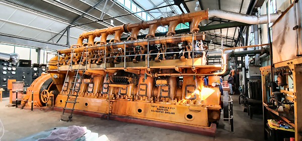
The 8VPE at the former Lismore Power Station, NSW, August 2019 © William Parrinder 2019.
William Parrinder emailed me after his visit to Lismore in August 2019. He said the group working towards the preservation of the former power station and its engines is still trying to acquire the building from the NSW state power company (Northern Rivers Electricity?) that owns it. The group was currently trying to get one of the other engines (a GM 16-567B, 1440 bhp at 750 rpm) going and then hoping to get the Paxman 8VPE back into running order by mid-2020.
In December 2023 I received news from Carl Heydon, a member of the group at the Lismore Powerhouse Museum. Unfortunately in the New South Wales floods of January 2022 the Paxman engine was completely submerged, as were seven other engines in the museum (Fullugars, English Electrics and a couple of Detroit Diesels). The group at the museum were in the process of cleaning, drying and lubricating the Paxman 8VPE and their other engines. Carl emailed for advice on removing an inlet valve seat in order to access a seized exhaust valve. The seat appeared to be primarily located by the inlet valve housing sleeve
Carl emailed me with a further update on 30th August 2025. He said: 'We are creeping closer to the eventual start. The oil tank has a new lid, as the original disappeared, and is about to be hot dip galvanized before re-installing under the floor. We are extending the breather and level gauge to help with minor floods. We managed to free up the pistons by undoing the big-end nuts and jacking connecting rods and have been rotating it with hoists and straps around the flywheel or front pulley with a happy 20psi oil pressure. Over the last few months we have refurbished the air start valves, compressor and receivers. With much excitement, on 28th August (2025), it rotated using the air start. Currently there are injectors only on the four centre cylinders with the remainder to be fitted next Thursday (2nd September). One of our two Fullagar 8Q engines has also been receiving love and we are assessing how to rig a temporary oil supply as we did manage to move the flywheel a small amount. We believe they are the only complete examples left.'
Carl hoped he would soon be able to send me a video of the 8VPE running.
Type 3VH A 3 cylinder Type VH, bought by Steve Green of Norfolk in September 2006, and acquired from him by Richard Keeble of Brantham Hall, Manningtree in summer 2008. The engine, including the bearings, is in very good condition but it has not been possible to find any identifying number on the engine or any of its main components. There is not even any evidence of a maker's plate having been attached to it originally. Not all three cylinder heads are identical and there are other small features which raise the possibility that this may originally have been a development engine. The engine was previously owned by Richmond Dodd and before that was installed (we think second hand) in Glenister's furniture factory at High Wycombe. Here it was coupled to a 60 cycle Crompton Parkinson alternator to drive American woodworking machinery which required 60 cycle current.
Two or three other examples have survived in Australia but details of their present whereabouts and condition are sketchy. See page Paxman Diesels in Australia. Further information would be welcome.
The Next Two Generations
Only four years on from introducing its vertical Heavy-Fuel-Oil engine to the market, Paxman launched its next generation of compression-ignition oil engines. After 1930 the focus of the Company's attention and efforts turned to its new monobloc engine range which is described on the page Paxman Heavy Duty Diesel Engines. Production of the heavy-fuel-oil engine, for the most part in its enclosed forced-lubricated form, continued up to 1935. By that time Paxman had got back on its feet after the disastrous financial collapse of AGE in 1932 and managed to develop its third generation of compression-ignition engines. The story of these medium and high-speed indirect injection types and their successors is told on the page Paxman Engines from 1934.
Appendix 1 - Local Authority Electrical Power Generation Installations
UK local authority installations included: Ashford (Kent) UDC Electricity Works, Armagh UDC, Llandrindod Wells UDC Electricity Works, Dunoon Electricity Supply Co Ltd, Northallerton Electric Light & Power Co Ltd, Newry UDC, Easingwold Electricity Works, Basingstoke Corporation Electricity Works, Royal Burgh of Rothesay Electricity Works, Bude Electric Supply Co, Tenby Electric Light Station.
AFRICA: Knysna, Bredasdorp, Piet Retief, Blantyre Municipality (Nyasaland, now Malawi). AUSTRALIA: Clarence River County Council, Gladstone (Queensland), Emerald Town Council, Rabaul & District Elec Supply Co Ltd, Lismore (NSW). NEW ZEALAND: Marlborough Electric Power Board at Blenheim. INDIA: Madura (near Madras).
Appendix 2 - Water Pumping Installations
UK Local Authority Waterworks: Metropolitan Water Board (London), Congleton Water Works (Borough of Congleton, Cheshire), Felixstowe and Walton Water Works (Suffolk), Eastbourne Waterworks, Oxford Waterworks, Great Yarmouth Waterworks Co (Horning Pumping Station, Norfolk), Banbury Water Co, Westgate & Birchington Water Co, East Worcestershire Waterworks.
AUSTRALIA: Metropolitan Water Board - Sydney, NSW; Marrickville Pumping Station.
References
1. Steam and the Road to Glory, Andrew Phillips, Hervey Benham Charitable Trust 2002 (ISBN 0 9529360 1 1) - pp. 476, 477.
2. Paxman Heavy-Fuel-Oil Engine catalogues (1927), No 931 p. 5, No 932 p. 4.
3. see www.theclydebankstory.com/story_TCSC02.php.
4. Paxman Heavy-Fuel-Oil Engine catalogues 952 and 987, p. 12, The Paxman Silent Valve (Made under Paxman & McIlraith's Patents).
5. Reported in Paxman World, Issue 1, January 1948.
Acknowledgements: My thanks to Alex Walford, formerly Principal Engineer - Mechanical, ALSTOM Engines Ltd, Regulateurs Europa, for his help with many questions and providing valuable additional information.
© Richard Carr 2006
Page updated: 01 Sep 2025 at 11:45