
Instruction Book for the
Working and Management of Portable Engines, & c.
Manufactured by Davey, Paxman & Co., Ltd., Colchester, England.
No 682 August 1913
Mainly for the benefit of owners and operators of surviving Paxman steam portables, this page reproduces the text of Paxman publication No 682, dated August 1913, entitled "Instruction Book for the Working and Management of Portable Engines".
Health & Safety It must be recognised that the Instructions below, and the steam portables to which they refer, were produced at a time when Health & Safety issues did not receive the attention which, quite properly, they do today.
Steam engine boilers are effectively pressure vessels containing large quantities of steam and scalding water, with accompanying risks of explosion, serious injury and even fatalities if safe working practices are not observed. The engines themselves have heavy moving parts without the guarding taken for granted on modern machinery. A boiler should only be fired if it has been examined by an accredited inspector and carries a current certificate, and then only under the supervision of someone with training and experience in the operation of steam plant.
The instructions below include references to asbestos packing and joints. In many parts of the world the use of asbestos is no longer permitted because of the major health risks involved. Much safer alternatives are now available.
Your attention is drawn to the terms of this website's Disclaimer
of Liability.
Introduction.
In presenting to our customers the following instructions for the working and management of our Portable Steam Engines, we would urge the importance of the various points being most carefully attended to, for although our engines are of the most efficient type, yet the economy which users naturally expect from such a high-class engine can soon be lost through careless working, or neglect. Not only will economy in fuel result from a thorough understanding of the proper working of the engine, but the repair bill will be reduced, and all accidents avoided.
When, however, renewals are required as the result of wear or neglect, these orders can usually be executed quickly if the engine number is quoted. In this connection we would add that we publish a catalogue (see Wearing Parts for Portable Engines page) giving a complete list of all the parts of our Portable Engines, together with an illustration of each, which catalogue should be in the hands of every user of our Portable Engines abroad.
Though primarily compiled for users of our Portable Engines, this Instruction Book will also be found useful by drivers and attendants of our Semi-portable, Undertype or Slide-valve Engines generally.
DAVEY PAXMAN & CO., LTD.
Instructions for Working Portable, Semi-Portable, Undertype Engines, &c.
Arranging the Engine. The engine should be arranged so that the base of all the wheels is quite level, and the ground must be made up to suit this if necessary, after which the wheels should be blocked with wood wedges to keep the engine steady when working. When thrashing, the engine should be so placed that the dust from the thrashing machine is not blown on to the engine. The flywheel should be exactly in line with the pulley on to which it is driving
PREPARATIONS FOR STARTING.
Boiler. The plug in the manhole cover should be removed, the funnel inserted, and the boiler filled with clean soft water until the water is half way up the gauge glass. While the boiler is being filled, the gauge glass and the test cocks should be open, and when water commences to run out they should be closed. If the water does not run out of the gauge glass cock when it is running out of the test cock (or vice versa), it shows that the bottom cock is stopped up and requires cleaning, which should be immediately done by taking out the small plug in front and cleaning the passage into the boiler with a piece of wire, afterwards replacing the plug.
When sufficient water is in the boiler as mentioned above, the cocks should be arranged as follows :- both test cocks closed; top gauge cock and middle gauge cock open to gauge glass and the bottom one closed.
If water has been standing in the boiler, see that it runs out of the test cock and the two bottom gauge cocks when these are opened, and that it rises to the right height again in the gauge glass after closing the bottom cock.
The water for feeding the boiler when working should be in a tub or tank near the feed pump, with the suction and overflow pipes both reaching into it. The water in this tank must always be absolutely clean ; this is of the greatest importance.
The water arrangements being now complete, the fire may next be considered, but before seeing to this, the tubes should first be carefully brushed out, then the ashes and clinkers removed from the grate, and the air spaces between the bars cleared. After this, the fire can be lighted by placing shavings, wood and small pieces of coal on the bars. When the coal is lighted, spread it over the grate so that the whole surface is covered, and keep adding small quantities of coal until steam is up. Keep a thin fire on the bars, and see that the whole of the grate is always covered.
Steam Pressure. The next part requiring attention to secure safety in working is the safety valve. Safety valves are to ensure that the pressure in the boiler shall never exceed the working pressure indicated on the gauge by a red mark. The safety valves may both be of the spring balance pattern or one spring-balance and one lock-up, but the spring-balance type is mostly used on portables.
See first that the valves are quite free by easing off the hand adjusting nut on the top of the spring balance so that as soon as the boiler has generated a few pounds of steam, the valve will blow off ; then screw the spring balance down until it locks on the ferrule which is fitted to the balance to suit the required pressure and to prevent the boiler being worked at a higher pressure than is indicated by the red line on the gauge. The lock-up valve is provided with a lever for the purpose of easing the valve on its seat ; to ensure that this valve is in working order, press the lever down, and allow the steam to escape.
Engine. See that all the working parts of the engine are clean and free, yet properly adjusted, and that every part is oiled and all lubricators in working order.
Oil the following while steam is being got up :- cylinder, main bearings, connecting rod ends, eccentric straps, bored guides, all pins, bearings, &c., of the valve gear and governor, feed pump and rod end. The slide valve and cylinder are lubricated by oil introduced into the steam before it reaches the slide valve. To fill this lubricator, close the bottom valve, drain the water off from the bottom tap, close this and fill from the top, then close the top and partially open the bottom valve, when the oil will be gradually introduced to the steam. Refill this every two or three hours when working, as described above.
In the case of main bearings fitted with chain lubrication, the oil well in the bearing block must be filled up until oil reaches the level of the return oil holes on the under side of the bottom brass. Before starting the engine, the chain should be examined to see that it revolves with the crankshaft ; this can be done by removing the sight hole plugs on the top of the bearing caps. In time, the oil in the well will become congealed, and will require renewing, which should be done at least every six months.
See that all the lubricators are filled, and that the syphon wicks have one end fitting in the tubes properly, and the lubricator cups covered, so that dust does not get in.
Put a little oil on the piston and valve rods, also on the bottom crosshead slides, open the cylinder drain cocks, and turn the flywheel by hand, to see that everything is quite free.
Mineral oil should be used, as this does not gum like vegetable oil, and consequently there is less friction and wear. Cheap oil is more extravagant in the long run and will ruin good machinery.
Feed Pump. Before starting, see that all pipes, passages, and suction hose are clear, and that all pipes (especially the suction pipes A) are screwed up tightly, and that the cock B between the boiler and pump is open to the boiler. If the suction pipe is not tight, or the rose is not covered with water, the pump will draw air, and no water will be lifted. In severe weather, if there is ice in the pump, pour hot water on the outside.
STARTING INSTRUCTIONS.
Starting. Open the cylinder drain cocks, turn the flywheel to bring the crank above the dead centre, that is, about quarter-stroke, then partly open the stop valve. Leave the cylinder drain cocks open until only steam blows out of these, when they may be closed, the stop valve fully opened, and the engine will run up to its full speed under the control of the governor.
WORKING INSTRUCTIONS.
Boiler. Two things are of the utmost importance for safe working, viz., the correct working of the safety valve, {which must blow off when the pressure tends to rise above the working pressure indicated on the gauge), and the water level in the gauge glass.
The safety valve should be frequently tested by slightly unscrewing the spring balance adjusting nut, when steam should immediately blow off if the valve is not sticking ; then the spring balance should be screwed down again to suit the working pressure. If the valve does not work properly, it must be attended to as soon as work is finished and the boiler pressure drops.
The water level must always be kept as near to the middle of the gauge glass (or the index on it) as possible to ensure the firebox top always being covered by water, and the gauge cocks must be frequently tested whilst the engine is at work, to see that they are in perfect order.
When working, the top and middle cocks of the gauge glass should be open to the boiler, and the bottom blow-off cock closed. To ascertain whether the top cock is working properly, close the middle cock and open the blow-off cock, when the water should be blown out of the gauge glass and steam should follow. To test the middle cock, close the blow-off cock and open the middle cock, when the water should immediately rise to its normal position in the gauge glass. If these do not act as described, they must be cleaned out, as instructed on page 5, as soon as the boiler is shut down.
If a gauge glass breaks, shut off the top and middle cocks immediately, and then a new glass and new rings may be fitted.
Test Cocks. These are a check or stand-by for the gauge glass. When the bottom one is opened, water should always be blown out, and when the top is open steam should always escape, and this ensures that the water level is between the two. These cocks must be used when the gauge glass is broken, or the gauge does not work properly. If the test cocks do not work, they should be cleaned out the same as the gauge glass cocks.
All these cocks have stuffing boxes or glands, which should be packed with asbestos.
Low Water. If from any cause the water should have entirely disappeared from the gauge glass and the bottom test cock only blows steam out, the fire must be at once taken out (It should not be extinguished by throwing water into the firebox, as this is very injurious to the plates). When the boiler has cooled down, it must be re-filled, as previously described, to its proper height before the fire is lighted again, and of course it must be seen that the pump and water supply are in order.
Fusible Plug. To prevent accidents in consequence of low water in the boiler, a fusible plug is fitted in the firebox crown. This plug is filled with lead, which melts as soon as the top of the fire-box is uncovered, allowing steam to enter the firebox and put out the fire. A new plug must afterwards be put in, or the old one taken out, filled with lead again, and replaced.
Boiler Feed. The gauge glass indicates the water level required in the boiler, and the feed apparatus has always to maintain this level. Every engine is fitted with a feed pump driven from the crankshaft, and may also be fitted, when specially ordered, with an injector, so that if the pump goes wrong the alternative method of feed can be used.
Pump. The pump having been attended to before starting, as previously described, it is essential to see that it is working properly as soon as the engine has started. The pump delivery has two paths, one to the boiler, and the other through the overflow cock C to the suction tank. Open the overflow cock C fully, and all the water should be discharged to the tank ; this shows the pump is working. If this cock C is now closed completely, all the water will be discharged into the boiler, and if this is too much, the water in the gauge glass will rise above the working level, in which case in order to keep it at the correct level the overflow cock C should be partly opened. The working position of this cock will soon be found by experiment. It is essential that this correct position should be found by the driver, so that the boiler is provided with a steady feed, to ensure a fixed working pressure of the steam and economy of fuel.
 Pump Troubles. To avoid troubles with the pump, keep the feed water absolutely clean.
If water is not discharged through the overflow pipe D when this cock C is full open, or does not maintain the water level in the boiler with this cock C adjusted, the pump is not lifting its water. Ascertain therefore if the holes in the suction rose are stopped up, or are not covered by water in the suction tank. See also if the overflow and suction pipes D and A are clear, and the latter screwed tightly to the pump. When the plunger is leaking, re-pack or tighten the gland L.
There only remain the valves, which may be dirty or stuck ; if the latter, strike the pump box with a piece of wood, and this may start them working. If this does not put things right, the cock B next to the boiler must be closed to shut off the boiler, and the heater cock E from the exhaust pipe also closed ; then the valve box covers F and G may be taken off, and the valves examined and cleaned, but this, of course, must never be done with the cock B to the boiler open. Should all these parts have received attention, and the water level still not be maintained, it may possibly be that the passage to the boiler is choked up, and this can only be cleaned out when there is no pressure in the boiler, by unscrewing the brass plug K provided for this purpose.
Should the check valve stick open and water commence to blow out from the boiler, close immediately the cock B next to the boiler, then examine and clean the valve by removing cover F.
Feed Heating. The pipe H and cock E connecting the exhaust pipe to the pump overflow pipe D enables the overflow water returning to the tank to be heated by the exhaust steam. This hot feed means economy in fuel and longer life for the boiler plates. Care should be taken that no grease is pumped into the boiler, as this is very injurious ; therefore keep the feed tank clean.
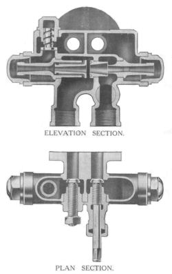
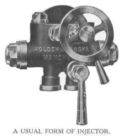 Injector. An injector (which can be fitted when specially ordered) is the simplest method of feeding the boiler, and is also very economical, as the steam used heats up the feed water. It will deliver hot water to the boiler due to this heating at a temperature of from 160 to 212 degrees Fahr., varying according to the pressure and the quantity delivered, and will work with pressures ranging from 20 lb. to 220 lb. per square inch.
The illustrations show the usual pattern of injector fitted to our portable engines.
To work the injector, open the suction valve full, then the steam valve, then gradually close the suction until the overflow water just stops. Should the water delivered to the boiler be too much, decrease this by further closing the suction valve.
 A stoppage of the injector may be due to any of the following causes : The suction pipes not being air-tight, the water in the feed tank being dirty or too hot, in which latter case the cock from the exhaust pipe to the tank must be closed when the injector is working. The injector should not be allowed to get too hot, but should this happen it must be cooled by pouring water on it. If this should occur through the check valve leaking and allowing hot water to get to the injector from the boiler, the check valve must be taken out and re- ground.
In addition it may be found that the internal parts of the injector are choked up, in which case it must be taken to pieces (after closing the steam and water connections to the boiler) and any deposit removed by soaking the parts in a solution of 1 part of muriatic acid in 10 parts of water. The suction lift should not be too great, and if the water is under pressure it should be throttled down, and in starting the steam valve should be opened first, and not last as described when the injector lifts its water.
Firing. To ensure economy in fuel, steady steam pressure, and long life for the boiler, the fire should be kept thin, 3 to 6 inches, the grate entirely covered, and the coal put on in small pieces. Except of course when actually stoking, keep the firedoor shut, or leaky tubes and ruined firebox plates will result. With good coal, the fire need only be cleaned once a day, but with inferior coal, clinkers must be removed from the bars frequently, otherwise the draft and the steam pressure will not be maintained.
If the pressure rises too high, lower the damper in front of ashpan, and if necessary, push the fire back to the tube plate.
Engine. While the engine is running, it is most essential that all the parts should be sufficiently lubricated. See that all the lubricators are full at starting, and that they are not allowed to get empty. If any bearings become hot, although the lubrication is satisfactory, see if they are adjusted too tightly, and if so, slacken them slightly ; but if they still heat up, examine the brasses and oil holes, and remove the dirt which is probably the cause of the heating.
As the parts get worn, adjustment is required, and any knocking which is noticeable when passing the centres means that some adjustment is necessary. The connecting-rod brasses are adjusted by means of cotters, and the main bearings by cap studs.
To adjust the brasses on eccentric straps, take them out, and file the edges quite square, replace them, being very careful that they are quite clean and oiled and that they are not tightened up too much, or heating will result, which means quick wearing of the brasses, or permanent injury to the shaft or pins. When the connecting-rod cotter has been adjusted right down, take it out and insert a thin liner sufficient to bring the cotter to the top again when the bearing is adjusted correctly.
Glands. The piston rod, valve spindles, and pump-plunger stuffing boxes must always be carefully packed and the glands suitably tightened to prevent leakage. To add new packing, unscrew the nuts and draw back the gland, put in the packing, and tap it up with a piece of wood ; then replace the gland, and screw up the nuts, but be careful that both nuts are screwed up to the same extent, so that the gland is not canted over. Hemp and various other packings are now in use to suit all requirements, but whatever type is used, it should prevent leakage without the gland having to be screwed up too tightly, thus causing excessive friction.
INSTRUCTIONS FOR STOPPING.
Shutting down. When the engine is in daily use, and stopping at the end of the day's run, get the water just above normal level to allow for waste, and have the fire as low as possible. Afterwards withdraw clinkers and ashes, quench with water in the ashpan, and close ashpan door. Close the engine stop valve, put the lubricators out of action, and open the cylinder drain cocks. Close gauge glass cocks to boiler, and open bottom cock to empty the gauge glass.
GENERAL INSTRUCTIONS.
Boiler. It is of the utmost importance that clean water is used for the feed, and that the boiler is cleaned out periodically. Deposit on the tubes, firebox top, and round the bottom of the firebox causes high fuel consumption, overheated plates, and boiler explosions.
To ensure safety and economy in working, blow out the water at least once a fortnight, or, if any impurity is suspected, once a week. To do this, take out the fire, and when the pressure has dropped to about 15 lb., open the blow-off cock. The pressure given is sufficient to blow out deposit, but the water should not be blown out at a higher pressure, as this means rapid and injurious cooling of the boiler.
Suitable mudholes and manholes are fitted, which must be opened, and by means of the rake provided, all deposit taken from the firebox top and sides, tube plate, and tubes. To take off the covers, remove the nut and crossbar, push the cover in, give it a half twist, and it can be pulled out. There is also a plug at the bottom of the smoke-box tubeplate, which may be removed, and the bottom of the barrel scraped, After all deposit has been loosened, wash the boiler out thoroughly with clean water, carefully replace the various covers with asbestos ring joints, and see that all nuts are perfectly tight.
When the water in the gauge glass looks dirty when working, pump extra water into the boiler to raise the water level, then open the blow-off cock and blow out until the water level is lowered again, This may be done several times a day, and blows out sediment which would otherwise form a deposit on the tubes and plates.
Where hard water is used, a small quantity of soda dissolved in warm water and added to the feed water from time to time prevents scale in the boiler, and the sediment formed may be frequently blown out as described above.
The boiler tubes should be frequently brushed out to keep them free from soot. This only takes a few minutes, and the economy in fuel obtained from this precaution is considerable.
If the engine is to be moved to another place, blow out as described on preceding page, lower the chimney, and if necessary remove the ashpan.
In frosty weather, empty the boiler, take the suction and discharge pipes out of the tank and empty the pump. The pump may always be emptied by giving the flywheel a few turns. See that the gauge glasses are empty.
Engine. The engine should always be kept clean and free from dust and grit. Some parts may be cleaned whilst running, but the working parts should be carefully attended to when standing. Keep all dirt away from working parts and lubricators. Examine the lubricators regularly for any defects. If the engine is to be left standing, clean and grease all the bright parts, remove cylinder cover and grease the inside of cylinder thoroughly, and cover the engine over if it is left in the open.
 Alteration of Cut-off. To alter the cut-off of the engine to suit the load, proceed as follows :-
The cut-off for maximum economy should be as early in the stroke as the load on the engine will permit. It will be seen that the eccentric has a stud M screwed into it, which passes through a slot N in the expansion plate P keyed to the shaft. The end of the stud has a pointer and a nut R for tightening up the eccentric S to the plate. The slot of the expansion plate P is marked for various cut-offs for each direction of running, and to vary the cut-off it is only necessary to ease the nut R and move the eccentric S across the slot N until the pointer is opposite the required cut-off, then tighten up the nut again. The earlier the cut-off, the greater is the expansion of the steam, which means greater economy in steam and consequently in fuel.
For double-cylinder engines, the cut-off for each side is varied as above.
Engines fitted with automatic expansion gear do not require altering as preceding page, as the cut-off is automatically varied by the governor.
Reversing. As before mentioned, the eccentric is bolted to a reversing plate, one end of which is marked OUT and the other IN. This plate is keyed to the shaft, and to reverse the direction of rotation, slacken the nut and move the eccentric across the slot until the bolt is up against the opposite end of the slot to that previously occupied, or nearer to this end, according to the cut-off required, then tighten the nut.
When leaving the Works, all engines are set to run IN, that is the top of the flywheel turning towards the cylinder, but of course the direction can be altered when required as above described.
In the case of double cylinder engines with throttle governors, proceed as in the case of the single-cylinder engines for each eccentric.
Automatic Expansion Gear. - Reversing. In the case of single-cylinder engines with automatic expansion gear, there is one fixed plate keyed to the shaft with one main and two expansion eccentrics beside it, all tightened together by means of a bolt passing through. This bolt is carried by one hole in the fixed plate, but each eccentric has two holes, one of which is used for the bolt when the engine is running IN, and the other when running OUT. The above diagram will help to explain the method of reversing.
The holes marked B1 and C1 are in the main eccentric and next to plate ; holes B2 and C2 are in the second eccentric from plate ; and holes B3 and C3 are in the third eccentric from plate. If the engine has been running IN, all the holes marked Cl, C2, and C3 have the bolt A passing through them. To run OUT, take out the bolt, turn the shaft to bring hole A in the plate opposite hole B1 and push in the bolt. Now turn back to B2, and push the bolt in this hole, then turn the other way again to B3 and push the bolt right through, put the nut on, and then the engine will be ready to run again.
If the engine has been running OUT, and it is required to run IN, take out the bolt, and move as above to holes C1, C2 and C3 and tighten up as before.
Illustration on page 17.
Illustration on page 18.
Setting Valves. The illustrations on pages 17 and 18 show the arrangement of governor gear &c., with governor in top position and sectional arrangement of cylinder with valves, piston, &c., in their relative positions.
| A - Steam chest. B - Piston. C - Main slide valve. D - Port plate. E - Automatic expansion valve. F - Stops for holding port plate in position. M - Eccentric rod to be coupled to long-throw eccentric. N - Top position of governor arm. |
G - Governors. H - Horizontal lifting lever. J - Rods for lifting expansion link. K - Expansion link. L - Eccentric rod to be coupled to short-throw eccentric. O - Middle position of governor arm. P - Bottom position of governor arm. |
First place the main slide valve C in position, fixing the locknuts so that the valve has no end-play, but is free to lay up against the cylinder face, the cut-off edges being C1 and C2. The port opening (or in other words the "lead") should be equal when the engine is on the front and back centres.
Then place the port plate D between the stops F, and be careful to see that whilst having no end-play, it is free to move, the action of the steam keeping it steam-tight against the back port face of main valve C.
To finally set the automatic expansion valve E, place the crank on one of the dead centres, then lift the governor with its system of rods into top position, as shown on page 17, and set valve E so that its cut-off edges come line to line with those in the port plate D, i.e., in position as shown on page 18. Then turn the engine round to the opposite dead centre, and if the relative position of the ports should not be the same as on the other dead centre, adjust valve E so as to divide the difference and to render both positions as much alike as possible.
 Governors. Whatever type of governor is used, it is very essential that all the working parts should be clean and well lubricated, so that no unnecessary friction is put on the governor, as such friction means more work and consequently bad regulation. The illustration at side shows a very usual form of throttle governor. In fixing this in position, care must be taken not to bend the spindle D, otherwise the governor cannot work satisfactorily. To adjust the position of throttle valve in chest, remove cap A and raise or lower the valve by means of the lock-nuts. The speed of the engine may be altered within certain limits by screwing the adjusting screw E up or down. The gland should be packed so as not to interfere with the motion of spindle D, otherwise the governor cannot work properly. Renew the packing in stuffing box occasionally. Keep the driving belt free from grease and tight enough to prevent slipping. The throttle governor is set at our Works to give the maximum power at the correct speed, and to control the speed of the engine when running on no load at full boiler pressure.
With all engines fitted with automatic expansion gear, the governor is provided with an oil dashpot, and for steady working the latter should always be full of oil. In filling, first see that the piston is at the bottom of the dashpot before pouring in the oil, and the oil bye-pass thumb-screw adjusted so that the governor is steady under all conditions.
(Note: The images on this web page have been reduced in size and compressed to minimise download time. If you are responsible for the restoration or maintenance of a Paxman steam portable and need to see more detail in any of the images, please contact me. Larger versions are available and I can send these as email attachments.)
Page updated: 06 MAR 2006