
Paxman Benzine Engines
Paxman started to develop its first internal combustion engines in either late 1903 or early 1904. These were oil engines running on 'light spirits', and gas engines. A 20 bhp prototype light oil engine was completed in April 1904. The oil and gas types were of very similar construction (horizontal, open crank) apart from fuelling and ignition arrangements. The gas engines soon began to sell in good numbers, with over fifty orders being received in 1905. The Company's trials of its early oil engines, described as 'benzine engines' in the surviving copy order books, met with mixed results. It took some time to overcome fuelling deficiencies and develop an engine that could be marketed with confidence. It would appear that from mid-1907 the Company began to receive small numbers of oil engine orders. Unfortunately records of oil and gas engine orders received before 1911 have not survived. Records thereafter show that the gas engines sold much more successfully than the oil types, a large proportion being for overseas customers.
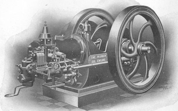
20 bhp Paxman Oil Engine, as illustrated in a 1905 Paxman catalogue. The 1904 prototype perhaps?
Immediately below is the text of a Paxman Benzine Engines publicity booklet. The cover of the copy from which the text is taken is missing (and the first and last pages?) so there is no record of its Paxman Publication number or date. It was almost certainly produced between 1905 and 1914. The illustrations referred to in the text below are not reproduced on this page.
Further down the page are details of a couple of surviving Paxman benzine engines.
The Paxman Benzine Engines.
Design. This type of engine is specially suitable for running on such light spirits as benzine, benzoline, petrol, gasoline, naptha, &c., of a specific gravity of not more than ·8. Its design is being constantly revised, so as to embody the latest improvements ; all illustrations, therefore given in this catalogue must not be taken as binding in detail. Particular attention is paid to the accessibility of the different parts in all sizes, and in designing our engines we have never lost sight of the fact that they should be of so simple a character that they can be properly looked after by the average engine attendant.
Carburetter. This is of extremely efficient design, and gives the greatest possible satisfaction with the light spirits for which it has been designed.
The Bed. The bedplate is an extremely massive casting, extending beneath the cylinder as far back as the combustion chamber, thus supporting the cylinder along the whole working length, and ensuring perfect freedom from vibration and movement. It is well ribbed, and an oil trough is formed all round the base to prevent oil reaching the foundations. This casting is accurately machined to receive the cylinder liner, crankshaft and sideshaft bearings. The three very small sizes are built with overhung cylinder.
The Cylinder. The cylinder is fitted with a loose liner, made of specially hard, close-grained cast-iron, so arranged that the outer end is free to expand and contract with the varying temperature of explosion. Except in the smallest sizes, the breech end is also removable, and separate from both cylinder jacket and liner, and has been designed to overcome what was hitherto a weakness in gas-engine design. In this construction, the inner and outer walls are tied by the exhaust and inlet passages, stout ribs supporting the back of the combustion chamber, by which arrangement the breech end is relieved of all internal casting strains. The inner and outer walls are also connected by a number of substantial steel bolts, the whole arrangement being sufficiently elastic to accommodate itself to the working strains due to pressure and the varying temperature of explosion.
The water jacket is provided with large inspection doors, through which any deposit may be removed.
It will be seen from the small illustration at the side that all valves in the Paxman design open directly into the combustion chamber, and not into pockets bolted to or cast on the cylinder. In other engines designed with pockets in the cylinder, it is extremely difficult to ensure that the exhaust gases are completely expelled at the end of the exhaust stroke ; whereas with our design there are absolutely no pockets in which the flame can lurk, and the cylinder is consequently completely and thoroughly scavenged ; in fact it is shown by the indicator that there is a slight vacuum at the end of each exhaust stroke, which ensures that a new charge entering the cylinder is not adulterated with the products of the previous explosion. More power is thus obtainable from the engine, and one of the most fruitful causes of pre-ignition is done away with.
Bearings. The crankshaft bearings are of the best gunmetal, of ample size and accurately machined ; but on size "J" and upwards the shells for the bearings are of cast-iron, lined with special anti-friction metal. The crankshaft bearings are so designed that the thrust is taken by the frame. All bearings are adjustable.
Piston. The piston is of the best close-grained hematite iron, with at least four loose rings, easily renewable when necessary.
Pulley. All engines of the industrial type are provided with suitable driving pulley. Engines of the electric-lighting type are only supplied with pulley when this is specially ordered, but space for our standard size of pulley is provided on the shaft between the flywheel and the outer bearing.
Valves. All valves work in loose seatings, which fit into accurately bored and ground recesses in the combustion chamber so that no jointing material is required, and the seatings can be readily removed by simply unscrewing a couple of nuts. It will be seen from the illustration of the cylinder that the valves are very accessible. The exhaust valve is placed at the bottom of the combustion chamber, and can be easily examined or removed.
Flywheels. Engines from size "C" to "H" inclusive are stocked with two flywheels. Engines from size "J" to "N" inclusive are stocked with single flywheel and outer bearing. We can supply the smaller engines from size "E" to "H" inclusive with single flywheel and outer bearing at an extra charge, and in the cases of sizes "J" to "K" inclusive we can modify our standard arrangement by fitting these engines with two flywheels. These flywheels are sufficient for ordinary industrial purposes, where a variation in speed of 5% between no load and full load is sufficiently close regulation for satisfactory working.
Engines for "Electric lighting" are fitted with one extra heavy flywheel of large diameter (to ensure regularity of running), extended crankshaft and outer bearing.
Connecting Rods. These are steel forgings, accurately machined, and finished bright all over, fitted with heavy bearings having large wearing surfaces. Except in the smallest sizes, the large-end bearings are lined with special anti-friction metal. The small-end bearings of all sizes are of best gun-metal.
Gear Wheels. The gear wheels for actuating the sideshaft and governor are machine-cut, and run in enclosed oil baths.
Sideshaft. The sideshaft is of mild steel, finished bright, and supported in bearings of ample length. The cams are all milled to standard pattern.
Governing. The speed is controlled by a very sensitive rotary governor, on a combination of the "hit and miss" and "regulation of mixture" principles, whereby the gas consumption is regulated strictly in accordance with the power taken from the engine. The governor is driven by machine-cut gears, and an arrangement is provided whereby the speed may be altered considerably either above or below the normal. The small size "B" engine is fitted with inertia governor.
Crankshaft. The crankshaft is of Siemens-Martin steel, machined from the solid forging, and finished bright, the balance weights being securely attached to the rims of the cranks. By this method, the engines run much more regularly, and unequal strains on the rims of the flywheels are avoided.
Ignition. The ignition of these engines is effected by means of a magneto, fitted with a timing device, which can be adjusted while the engine is running. This enables the time of ignition to be retarded at starting, thus avoiding any possible risk of a back-fire ; whilst as soon as the engine is fairly under way, the point of ignition can be advanced, so as to give the early firing which is required to obtain the full economy from the spirit used.
Lubrication. The most careful attention has been paid to the lubrication of the working parts of the engines. The crankshaft and sideshaft bearings of all engines from size "E" to "N" inclusive are fitted with self-oiling chain lubrication. The lubrication troughs for these bearings are designed so as to be easily cleaned, and inspection doors are provided.
Forced lubrication is fitted to the cylinder on all engines of size "Y" and upwards. The crankpin bearing of all engines is provided with dust-proof centrifugal ring-oiler, as shown in the small illustration at side. The piston pin is positively lubricated by means of an adjustable sight feed lubricator fixed on the cylinder, which delivers oil to a trough attached to the piston, whence it flows directly on to the pin.
Starting Apparatus. With engines of size "Y " and upwards, a starter is necessary. We recommend the compressed air starter with hand-power compressor, especially for the larger engines, on account of its reliability, and the ease with which it can be used, enabling our benzine engines to be got under way with the same certainty as a steam engine. For the smaller engines, a pump starter using petrol or benzine is often supplied.
Exhaust Silencer and Set of Spanners are provided with each engine.
Air Silencer. An air silencer is provided with size "E" engine and upwards.
Benzine Tank. The necessary tank for containing the spirit, with pipe to connect same to carburettor, is supplied.
Renewals. All parts are made to templates, so that in the case of breakage or wear of any part it can be immediately renewed from stock, if the engine number is quoted.
Spare Parts. The following spare parts are supplied with each engine: one complete set of springs, one piston ring, and one tool for grinding valves.
Powers. The powers given on page 10 are on the assumption that benzine of a specific gravity of ·7 is used, and that the engine is to be installed at sea level. When installed at any considerable height above sea level, the b.h.p. developed by the engine will be reduced by about 4% per 1,000 feet altitude. All engines are thoroughly tested in our works at the maximum load before despatch.
Consumption. The consumption of spirit varies from ·6 pint in the larger sizes to ·7 pint in the smaller engines.
Note. The foregoing description of our benzine engines is liable to alteration from time to time in consequence of improvements which we are always striving to effect.
Paxman Benzine Engines.
| Size | Brake Horse-Power on Benzine | Revs. per minute | Flywheels | Pulley | Capacity of Water Cooling Tanks (galls.) | Approx. Weight Net (cwts.) | ||||
|---|---|---|---|---|---|---|---|---|---|---|
| Max Load | Working Load | No. | Diam. | Width | Diam. | Width | ||||
| B | 2.5 | 2.2 | 300 | 1 | 2' 5½" | 4½" | 8" | 6" | 85 | 9½" |
| C | 5 | 4.5 | 280 | 2 | 3' 0" | 4½" | 12" | 6" | 168 | 19 |
| D | 7.75 | 7 | 280 | 2 | 3' 3" | 4½" | 14" | 8" | 210 | 22 |
| E | 10 | 9 | 300 | 2 | 3' 6" | 4¾" | 18" | 8" | 250 | 26 |
| F | 12.5 | 11 | 300 | 2 | 3' 6" | 4¾" | 18" | 8" | 336 | 27 |
| G | 15.5 | 14 | 270 | 2 | 3' 10" | 5" | 27" | 10" | 420 | 36 |
| H | 19 | 17 | 270 | 2 | 4' 4½" | 5" | 27" | 10" | 500 | 40 |
| J | 23 | 20 | 250 | 1 | 5' 4" | 7½" | 36" | 11" | 750 | 52 |
| X | 28 | 25 | 250 | 1 | 5' 4" | 7½" | 36" | 11" | 750 | 54 |
| Y | 35 | 31 | 240 | 1 | 5' 6" | 8" | 36" | 12" | 840 | 72 |
| K | 40 | 36 | 240 | 1 | 6' 0" | 8" | 42" | 12" | 1000 | 77 |
| L | 50 | 45 | 220 | 1 | 7' 0" | 8" | 45" | 14" | 1000 | 120 |
| M | 60 | 54 | 220 | 1 | 7' 3" | 8½" | 48" | 17" | 1680 | 130 |
| N | 70 | 63 | 200 | 1 | 7' 3" | 9½" | 52" | 19" | 2100 | 165 |
The above range of engines are supplied with : —
Variable magneto ignition. Embedded cylinder, size "E" and upwards. Carburetter.
Continuous centrifugal system of lubrication to the crankpin, size "E" and upwards. Balance weights to crank.
Sight-feed drop lubrication to cylinder up to size "X." Forced lubrication with size "Y" and upwards.
Splash Guards. Crankshaft cut from solid forging.
Independent air silencer and air regulator with size "E" and upwards. Exhaust silencer.
Crankshaft bearings and sideshaft bearings fitted with Paxman's improved system of self-oiling chain lubrication on size "E" and upwards.
Oil trough is cast round bedplate of size "E" and upwards. Benzine tank and pipe to carburettor.
Surviving Paxman Benzine Engines
 No 17430 A 'C' Type engine ordered on 18th January 1912 by John Blyth & Co and dispatched on 4th April that year to Moffat Virtue of Sydney, Australia (agents). With a cylinder of 5" bore x 10" stroke, the rated output was 4½ - 5 bhp at 280 rpm. It has two flywheels, each 3' diameter x 4½" wide, and a driving pulley 12" diameter x 6" wide. The original order specified that it was to be supplied with a shallow bed suitable for mounting on transport to be used as a portable engine.
After return to the UK, No 17430 was nicely restored (pictured right) to working order by the late Russell Weavers of West Mersea, Colchester, and was part of his impressive collection of old stationary engines. Although the engine was originally built with a Bosch low-tension magneto ignition system, driven by the side shaft, Russell fitted a Bosch high-tension magneto and sparking plug. (Interesting to note that Bosch magnetos, being made in Germany, became unavailable to Paxman after the outbreak of war in 1914.)
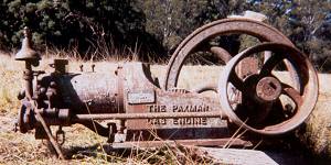 No 17828 (pictured left), was brought to my attention in October 2001 by Tony Marvin of Kurrajong, NSW, Australia. It was discovered after being abandoned for at least 45 years in the Australian bush. Tony, who had previously worked as a service engineer on Ruston and Paxman engines, suspected this gas engine was originally a benzine engine. The order book appears to confirm his suspicions, and reveals many similarities to No 17430 described above. It was ordered by John Blyth & Co of Sydney on 9th August 1912 and dispatched to Australia on 27th November 1912. The order for No 17828 is recorded as one for an 'E' Type benzine engine, 6.7/8" bore x 13" stroke, with a rating of 7 - 7¾ bhp. A 'D' Type was also part of the order. In actual fact No 17828 has a 7" bore x 14" stroke. There are various possible reasons why the bore and stroke are different from those specified in the order book.
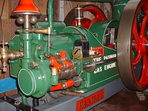
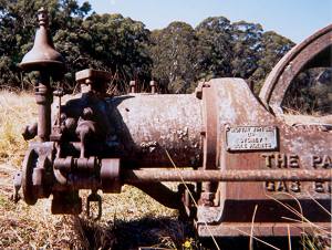 To the right is a more detailed picture of the governor and valve gear on No 17828. As on No 17430, the two inlet valves are on the side of the cylinder whereas on the larger engines the inlet valves are on top. The right inlet valve admits air only and is not governed. The left inlet valve is controlled by the 'hit and miss' governor, admitting fuel and air as required to maintain the required speed and power output. On all engines the exhaust valve is on the under side of the cylinder. Part of it can be seen in the photograph - the D shaped loop near the ground, below the cams on the side shaft. To the left of the inlet valves is the vertical drive shaft for the governor. The fly weights are under the 'pixie hat' at the top of the shaft. On the front of the engine, immediately to the left of the flywheel, is the 'Moffat Virtue of Sydney' agent's plate, identical to that on engine No 17430.
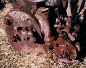 No 17828 has a fixed cylinder head (see left), as does No 17430. This was usual for the smaller engines, while on the larger engines the breech end of the cylinder was removable. Tony told me all the indications were that his engine originally had a low-tension magneto, not hot tube ignition as first thought, so he decided to go with magneto ignition.
In the centre of the photograph the lower section of the vertical drive shaft for the governor can be seen, and at its bottom end the skew gear drive from the side shaft. To the right of the vertical shaft is another view of some of the valve gear.
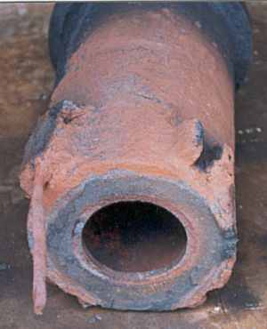
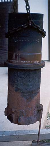 For some time Tony had planned to remove the cylinder liner so that the corroded retaining bolts could be replaced with stainless steel ones. After various unsuccessful attempts to remove it, Tony emailed in early March (2002) to say "We have at last got the liner out of the gas engine block. Hurrah!! . . . cylinder is held in by tee headed iron bolts - not much left due to corrosion, will replace by stainless ones. Dismantling now finished so we on the way up." Tony mailed two photographs, one to the right showing the liner after removal. The other photograph, below, shows the cylinder head end of the liner with one of the old tee headed bolts still in place. To the right of the old bolt, clearly visible, is the pair of lugs on the liner for positioning and holding another of the four tee bolts originally fitted.
As regards the ignition system Tony commented: "Our engine has the original carburettor and the igniter has been found! So we will be able to construct the missing mechanisms. I have an old type HT magneto so we will end up with quite an unusual hybrid as follows: A high tension mag for a spark plug in the top of the cylinder and at the same time the linkage from the mag tripping the igniter which is connected to a 6 volt induction system !!" (The original carburettor on Russell Weaver's engine, No 17430, was missing and one was made using the body of an old brass tap and the float chamber from an Amal carburettor. That engine does have a spark plug in the top of the cylinder, as Tony intended to fit to No 17828.)
Tony Marvin was in his eighties when he commenced the restoration and, sadly, is no longer with us. He may have completed the restoration before his death. At one stage he was planning to purchase a new cylinder liner casting from India for the project. If you have information about the current location, owner or condition of No 17828, please do contact me with details. I would also be interested to learn of any other surviving examples of these early Paxman spark-ignition oil engines.
Photos of No 17828 courtesy of Tony Marvin.
Page updated: 29 NOV 2014