Blackstone & Carter's Spring Injection
Operation of the "Spring Injection" Device
This page supplements the details of Blackstone and Carter's patent "Spring Injection" given on the Heavy-Fuel-Oil Engines page. What follows is a summary of some of the advantages of the system and an explanation of its operation.
The advantages of "Spring Injection" were summarised in a Paxman catalogue as being:
- It dispenses with the high pressure oil system and its attendant troubles. Instead - a measured quantity of fuel is delivered by a governed pump, at a pressure not exceeding 10/15 lbs. per square inch, to a chamber on the cylinder head where it is imprisoned and only subjected to pressure just prior to injection.
- Injection takes place at a pressure of approximately 1000 lbs. per square inch instead of the abnormally high pressure usually employed. This produces a prolonged and almost perfect combustion with the following highly important results:-
- A low initial pressure coupled with a high mean effective pressure, reducing shock and strain upon the working parts to the absolute minimum.
- A consistently low fuel consumption at all loads.
- A clean and almost odourless exhaust enabling the engine to be employed in many places hitherto barred to oil engines (as for example - dairies, food product factories, laundries, cotton mills, etc.).
- A low initial pressure coupled with a high mean effective pressure, reducing shock and strain upon the working parts to the absolute minimum.
- The operation of the "Spring Injection" device is in no way affected by the engine speed - it functions perfectly whether the engine be just turning over or running at several hundred revolutions per minute. It is this characteristic that enables us to vary the speed of the PAXMAN engine under load.
- The oil suddenly escapes past the injection valve at full pressure, enters the combustion chamber in a steady jet and is then as suddenly cut off. The effect of this action is to obviate the dribble at start and finish that seems to be unavoidable with cam injection.
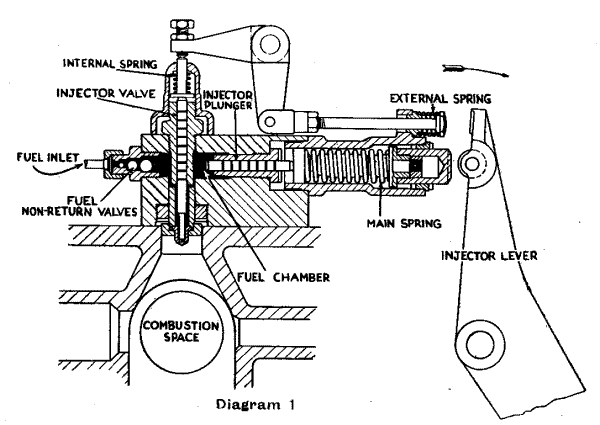
The following diagrams explain the action of the "Spring Injection" device.

In Diagram 1 above, the Injector Lever, which is operated by an eccentric on the half time shaft, has been withdrawn, and a measured quantity of fuel has been delivered to the Fuel Chamber from the governed fuel pump pushing the Injector Plunger and Main Spring member bodily outwards.

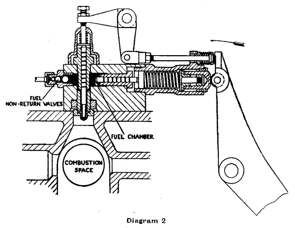
In Diagram 2 above, rotation of the half time shaft has brought the roller on the Injector Lever into contact with the outer portion of the Main Spring member, compressing the main spring, forcing the Injector Plunger against the oil in the Fuel Chamber and closing the non-return valves.
The oil in the Fuel Chamber is now imprisoned and under pressure. This takes place just before the piston reaches in-dead centre.
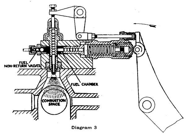
The Injector Valve is held on its seat by the combined action of an internal spring and an external spring - the latter operating through a rod and bell crank lever.

In Diagram 3 above, the tip of the Injector Lever has compressed the external spring slightly taking its pressure off the Injector Valve. The pressure on the oil in the Fuel Chamber is now sufficient to overcome the internal spring and lift the Injector Valve off its seat, when injection takes place. The fuel is thus under full pressure when the injection starts and there is consequently no dribble. The valve is open only so long as the oil is under pressure, and closes instantly on completion of the charge. There is consequently no dribble when injection stops.
Page updated: 29 APR 2002
