Paxman VP185 Turbocharging Arrangements
including a description of the 'Twin Box' 12VP185
To achieve its very high power-to-weight and power-to-volume ratios the Paxman VP185 engine is pressure charged, intercooled and aftercooled. A major innovation in the original 12 cylinder version was its two-stage turbocharging arrangement, contained within one large turbocharger housing or 'box' which sits on top of the engine. This page describes the original single box arrangement, the 'three box' arrangement which was developed for the 18 cylinder VP185 and a variant of the standard 12VP185's arrangement, the 'twin box' design.
Unless you are familiar with the VP185, it may be helpful to read first the description of this engine on the page Paxman Diesel Engines since 1934.
Pressure Charging
The maximum power output of a diesel engine is determined by, among other things, the amount of fuel it can burn within a given time. The amount of fuel that can be burnt within a set time depends on the amount of air available for combustion. In a naturally aspirated engine the amount of available combustion air is relatively small as it depends on the vacuum created in the cylinder during the induction stroke and atmospheric pressure. To provide substantially more combustion air most diesel engines are 'pressure charged' - the charge of air introduced into the cylinder during the induction stroke is fed in under pressure. This allows more fuel to be burnt during each power stroke, increasing an engine's power output by up to as much as four times or more. The most common method of pressure charging a diesel engine these days is use of an exhaust-driven Büchi turbocharger. On the Glossary page there are more detailed explanations of naturally aspirated, pressure charging and turbocharging.
Paxman's Pre-VP185 Practice
Prior to the VP185 Paxman's normal practice was to employ single-stage turbocharging using one large turbocharger, of axial flow turbine and radial compressor construction, usually of Napier, Elliott or Brown Boveri (now ABB) manufacture. This type of turbocharger has certain limitations. It tends to have narrow operating characteristics but the VP185 had to be capable of operating over a wide torque and speed range to meet the needs of its target markets and intended applications. It is also very expensive and heavy. Not only is the initial cost high but repair or replacement is expensive and time consuming and requires heavy lifting equipment. These considerations led the Company to carry out in-depth investigations into, and experiments with, alternative turbocharging arrangements. The result was a highly innovative (patented) two-stage turbocharging solution using multiple automotive-type turbochargers housed in a single water-cooled, gas-tight casing. The arrangement delivers good boost pressures down to the lowest operating speeds, providing the necessary air-fuel ratios for good combustion and high engine torque. The automotive-type turbochargers also have the advantages of much lower initial cost and being cheaper and quicker to replace on engines in service.
Use of Automotive-Type Turbochargers
It was Richard Hopper, one of Paxman's Stress Engineers, who came up with the idea of using automotive-type turbochargers. He was very conscious of the narrow operating characteristics of the large turbochargers previously used and was fully aware of the need for the new engine to be able to perform well over a wide speed range. He read a magazine article about a powerboat with two-stage turbocharging, using automotive-type turbochargers, which set him thinking about the possibility of adapting this arrangement for the much larger Paxman engine. Richard then did some performance calculations on his ideas which produced highly promising results. These he discussed with his colleagues, Barry Whitfield (Chief Performance Engineer), Ron Miller (Chief Stress Engineer) and Morriss Clover who had taken over as Chief Engineer in the summer of 1987. The discussions involved some lively debate during which Richard was challenged with various potential objections and had to fully justify his case. It should be said that this small group had worked together for many years and its members were on good terms with each another. However, they were all professional engineers whose natural instinct is to question new ideas, to subject them to detailed scrutiny and to demand objective scientific evidence of their soundness. Richard's careful arguments and calculations persuaded them that the idea should be taken further. The group then took the idea to Nigel Ramsden, Technical Director, who, in due course, was also convinced.
As an interesting aside, Richard has told me that his original idea was to use twelve turbochargers on the 12 cylinder engine. He envisaged using one high-pressure and two low-pressure turbochargers for a group of three cylinders. He was very aware that there were plans to develop an 18 cylinder engine after the 12 cylinder version and was therefore looking at an arrangement which could be used on both types. However, although the automotive-type turbochargers were vastly cheaper than the large ones previously used by Paxman, he realised and accepted that the engineering required for a twelve turbocharger system, such as the intercooling and aftercooling arrangements, would have been too complicated and expensive.
All VP185s, including the prototypes, have been fitted with Schwitzer turbochargers. Paxman had initially looked at using turbochargers from a couple of other manufacturers before approaching Schwitzer. The design work on the turbochargers for the VP185 was carried out at Schwitzer's Indianapolis plant in the USA, with the manufacturing being done at their Bradford plant, here in the UK. The Schwitzer blowers have been very successful, giving a much longer service life between overhaul or replacement than the large turbochargers fitted to earlier Paxman engines. Schwitzer was acquired by BorgWarner in 1999 and is now part of BorgWarner Turbo Systems.
The VP185 - Two-Stage Turbocharged, Intercooled and Aftercooled
The charge air system of all VP185s is two-stage turbocharged, intercooled and aftercooled. For the benefit of those unfamiliar with turbocharging technology a brief explanation of these features may be helpful.
Two-Stage Turbocharging
The standard 12 cylinder VP185's 'box' houses six automotive type turbochargers. Four of these are 'low-pressure' turbochargers which carry out the first stage of compressing the combustion air. The air compressed by these low-pressure turbochargers is then compressed again, during the second stage, by the two 'high-pressure' turbochargers.
Intercooled and Aftercooled
The ultimate aim of pressure charging is to feed as large a quantity of air as possible into each cylinder to maximise the quantity of fuel that can be burnt efficiently. However, when air, or any gas, is compressed its temperature rises and it expands to occupy a larger volume (assuming it remains at the same pressure). To increase the amount of air that can be fed into the cylinder it is therefore common practice to adopt intercooling. In single-stage turbocharging, after the charge air has been compressed it is cooled ('intercooled') before being fed, via the inlet manifold, into the cylinder during the induction stroke. In a two-stage turbocharging system, such as that of the VP185, the air is cooled twice. It is 'intercooled' after the first (low-compression) stage (i.e. 'inter' or in-between the first and second stage) then 'aftercooled' after the second (high-compression) stage, before being fed to the inlet manifold.
The 'Single Box' 12VP185's Turbocharger Housing
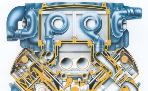
Cutaway illustration of the standard 12VP185's single turbocharger housing.
In the illustration above, the two high-pressure turbochargers of the single box 12VP185 are in the centre. On each side one of the low-pressure turbochargers is visible. The cooling water passages in the gas-tight casing of the turbocharger housing can also be seen. Below is a photograph of a standard 12VP185's single turbocharger housing or 'box'.
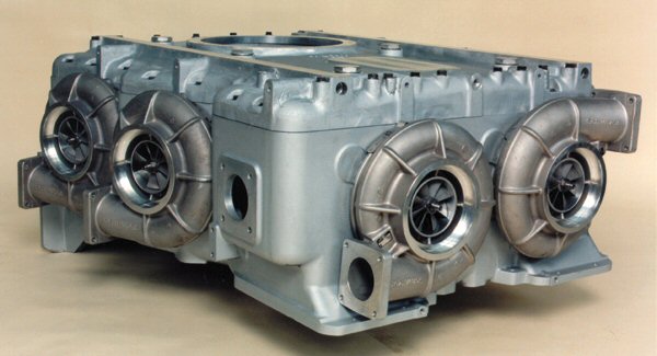
The standard 12VP185's single box, housing six turbochargers.
A fuller technical description of the standard 12VP185's turbocharging and intercooling arrangement appears in Paxman's 12VP185 brochures published in 1993 and 1995 and is reproduced at the foot of this page as an appendix.
The 'Three Box' 18VP185 and 'Twin Box' 12VP185
One of the design challenges when planning the 18 cylinder version of the VP185 was how to adapt the turbocharging and intercooling arrangement of the original single box 12VP185 to the larger engine. Instead of attempting to design a larger single turbocharger housing it was decided to use three housings or 'boxes'. Each box houses three turbochargers driven by the exhaust from six cylinders, three A bank and the three corresponding B bank cylinders. Following on from the development of the 18VP185's turbocharging arrangement has been the development of a variant of the standard 12VP185 known colloquially as 'the twin box 12'. This has two boxes of the same design as those on the 18 cylinder, as shown in the schematic diagram below, instead of the 12VP185's usual single box.
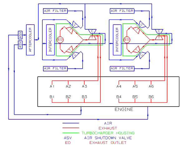
Schematic diagram of the Twin Box 12VP185's turbocharging, intercooling and aftercooling arrangement.
Each box on the twin box 12VP185 and on the three box 18VP185 houses two low-pressure compressors (turbochargers) and one high-pressure compressor (turbocharger). Ambient air drawn through the air intake filters is first compressed by the low-pressure compressors from whence it is discharged into the intercooler which is located under the box. From the intercooler the low-pressure air is fed to the high-pressure compressor. The high-pressure compressor of each box discharges into a high-pressure air pipe which feeds the hot high-pressure air to a single aftercooler. The aftercooler straddles the drive end of the engine on both the twin box 12VP185 and the 18VP185 and discharges the aftercooled charge air to the inlet manifolds.
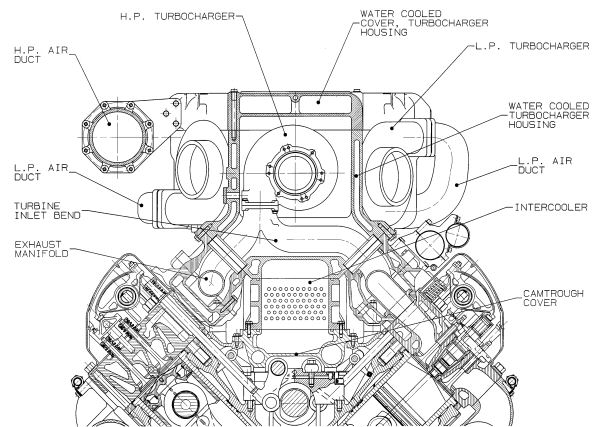
The sectional drawing below shows the location of an 18VP185 turbocharger housing, on top of the engine. The housings on the twin box 12VP185 are similarly arranged. The illustration shows clearly the position of the intercooler, located beneath the box in the vee of the engine.
Below is a photograph of an 18VP185's turbocharger housing with the cover removed. Front left is the high-pressure compressor and behind it, inside the housing, is the high-pressure turbine which drives it. At the back, rising up from inside the housing, are the exhaust outlets from the two turbines which drive the low-pressure compressors.
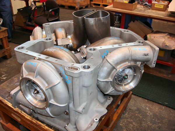
Photograph © Steve Cooper 2009.
Advantages of the 'Twin Box' Arrangement on the 12VP185
The major advantage of the twin box system, compared to the single box, is derived from the aftercooler. The same aftercooler is fitted to both the twin box 12VP185 and the 18VP185. It was originally sized to suit the 18 so on the twin box 12VP185 the volume flow rate of air over the cooling surface is only two thirds that on the 18. Air velocity is therefore two thirds that on the 18 and consequently the air is in contact with the cooling surface for 50% more time. This gives the aftercooler a superior performance on the twin box 12VP185, resulting in a lower air manifold temperature. The single box 12VP185 would benefit from being fitted with a larger aftercooler but this is not practical because of the positions of the high-pressure compressors on one side of the cooler and the governor on the other.
The second advantage is associated with the high pressure exhaust system. In single box form, the 12VP185 consistently exhibited the highest exhaust temperatures on cylinders A3 and A4. This is due to the tight bend on the entry to the high pressure turbine on the A Bank side of the engine. The twin box 12VP185 has a different exhaust arrangement. Instead of one high-pressure turbine being driven by cylinders A1 to A6, and the other by cylinders B1 to B6, the drive end turbine is driven by cylinders A1 to A3 and B1 to B3, and the free end by cylinders A4 to A6 and B4 to B6, as shown in the schematic diagram above. This allows the bends on the high-pressure turbine entry to be more generous than those on A Bank of the single box engine. In practice the twin box arrangement has evened out the exhaust temperatures.
Comparative Performances
Sprint ratings of the three versions of the VP185 are as follows:
SINGLE BOX 12 CYLINDER: 2,611 kWb at 1,950 rpm at ambient air and sea water temperatures of 25°C;
THREE BOX 18 CYLINDER: 4,000 kWb at 1,950 rpm at ambient air and sea water temperatures of 25°C;
TWIN BOX 12 CYLINDER: 2,667 kWb at 1,950 rpm at ambient air and sea water temperatures of 25°C. This is two thirds of the 18 cylinder version's sprint rating. Because of the benefit of the large aftercooler on the twin box version, Paxman could offer the same 2,667kWb sprint rating at the higher ambient air and sea water temperatures of 45°C and 32°C respectively.
Twin Box 12VP185 Orders and Applications
The first eight twin box 12VP185s were ordered by Tenix Shipbuilding, New Zealand. Build of the first engine commenced at MAN Diesel's Stockport factory but was completed at Colchester. The remaining seven of this order were built and tested entirely at Colchester. They were for main propulsion for four Royal New Zealand Navy twin-engined Inshore Patrol Vessels built by Tenix at their Whangarei yard. 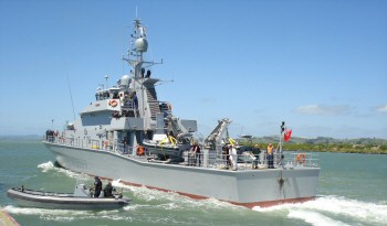 The first two vessels, HMNZS Rotoiti and HMNZS Hawea, were launched in 2007. The other two, HMNZS Pukaki and HMNZS Taupo, were launched in 2008. Tenix subsequently ordered a spare twin box 12VP185 engine for the RNZN. This was built at Colchester and despatched in early August, 2008.
Photo: HMNZS Rotoiti during commissioning. © Norman Iles, 2007.
The engines supplied to Tenix have a sprint rating of 2,500 kWb at 1,907 rpm under the tropical conditions of ambient air and sea water temperatures of 45°C and 32°C respectively, slightly below the maximum rating for the twin box type. Sea trials of the first Tenix vessel took place in 2007. Although the vessel was nearly 10% over weight during these trials, the contract speed was exceeded with 1 mm to spare on the fuel racks. The commissioning work in New Zealand was carried out by Norman Iles, a long-service member of the Paxman team at Colchester.
The first twin box 12VP185 gen-set driver was shipped by Paxman at the end of March 2009. The engine was for a generator set being packaged by Tilsley and Lovatt, and destined for an offshore gas platform off the coast of Qatar in the Persian Gulf. It is rated at 2,165kWb at 1,500 rpm at an ambient temperature of 45°C. Pictured below is the engine in the final stages of build at Colchester. Clearly visible at the drive (left hand) end of the engine is the large aftercooler - above Kevin Hammond's 'blue gloved' hand ! An unusual feature of the engine is its four Racor coalescers for breather re-ingestion which can be seen mounted high up at the free (right hand) end.
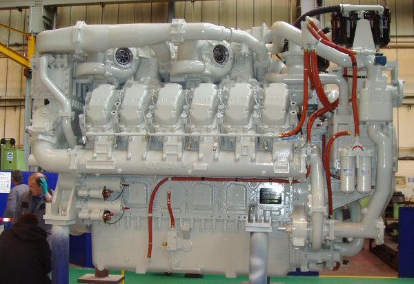
Twin box 12VP185 Gen-Set Engine for Qatar nearing completion at Colchester. © Ian Drake, 2009
Appendix
Description of the turbocharging arrangement of the standard 12 cylinder VP185 appearing in the brochure The Paxman 12VP185, GEC ALSTHOM Paxman Diesels publication PDP 185/1 3/93.
Exhaust System and Turbocharging
The 12VP185 has a two-stage turbocharged, intercooled and aftercooled charge air system. There are no electronic controls involved in the system nor are there any valves in either the exhaust or charge air systems - in this respect the system maintains the engine's central theme of maximising reliability by minimisation of parts. The turbochargers are automotive derivatives adapted to suit the 12VP185 layout. A pulsed exhaust system is used to drive two high-pressure turbochargers to give the engine a broad torque characteristic and wide surge margin. The exhaust manifolds of each cylinder bank are contained in a water-cooled, gas-tight casing. The two high-pressure turbochargers each expand into a pair of similar low-pressure turbochargers, making six in all. The hot turbine sides of the turbochargers along with the interconnecting ductwork is contained within a single water-cooled, gas-tight casing, referred to as the Turbocharger Housing. The rotating assemblies and compressor casings of the six turbochargers (which are all identical) form cartridges which mount directly into the side of the housing, the associated turbine casings being fixed to the housing. This arrangement enables any turbocharger to be replaced swiftly without recourse to heavy lifting equipment. The total arrangement of manifold casings and turbocharger housing gives the engine a gas-tight exhaust system with a cool surface, points which can be important from a safely aspect.
The above also appears in a later version of The Paxman 12VP185 brochure, GEC ALSTHOM Paxman Diesels publication PDP 185/1 8/95. The subsequent paragraph in the 1995 brochure reads:
On the air side, air is compressed in the four first stage compressors and flows through a raw water cooled intercooler to the two high-pressure compressors. From the high-pressure compressors the air passes to the aftercooler and then to the inlet manifold. Overspeed shut-down valves are fitted to the inlet manifolds.
The overspeed air shutdown system developed for the single box 12VP185 is, in essentials, retained in the twin box 12VP185 configuration. Due to space constraints, it proved necessary to accommodate the air shutdown valves within the twin box aftercooler outlet casing. However, function of the overspeed air shutdown system remains identical to that of single box 12VP185 engines.
Acknowledgements:
I am heavily indebted to Ian Drake, Chief Design Engineer of MAN Diesel Ltd at Colchester, for the extensive information and illustrations he has provided. Ian, under the direction of Nigel Ramsden, formerly the Company's Technical Director, led the team which designed the VP185 initially and has been the key person responsible for subsequent development of the engine. No one has a deeper knowledge of, or has had a closer personal involvement in, the design of this world-beating engine and its ongoing development. My thanks also to Norman Iles for permission to use his photograph of HMNZS Rotoiti during its commissioning and to Steve Cooper for permission to use his photograph of an 18VP185 turbocharger housing.
© Richard Carr 2009
Page updated: 02 AUG 2012
