
Paxman-Lentz Steam Engine - No 18581
Paxman's technical achievements in the field of steam engine building reached their zenith with the Paxman-Lentz. Around 130 of them were built at the Colchester works between 1907 and 1934 when the last was despatched. One of only two of these engines known to have survived is No 18581. Chris Hodrien, Technical Adviser of the International Stationary Steam Engine Society, considers this engine to be remarkable for its technical interest and beautiful condition. The other Paxman-Lentz survivor is No 18842 which is in an old teak sawmill in Bangkok, Thailand and more details about that engine can be found on the Surviving Paxman Stationary Steam Engines page. Sadly, a third Paxman-Lentz, No 22351, which remained at work in Hertfordshire until 1980 was scrapped c.1990.
On this page are some excellent photographs, taken by Colin Bowden, showing No 18581 before it was removed from Glenister's furniture factory at High Wycombe in 1996/97. It is good to have these pictures of a Paxman-Lentz in a real working environment. Accompanying the pictures are a brief history of the engine and technical information on this type. First, for those unfamiliar with steam engines, is an explanation of some technical terms which are used later on this page. If you are well-versed in the terminology, you can skip this section.
GLOSSARY
Compound: A steam engine with two cylinders, one high pressure (HP) and one low pressure (LP). Steam from the boiler is fed to the HP cylinder which has a smaller bore than the LP one. When the steam has completed its power stroke in the HP cylinder it has not yet fully expanded and is still capable of doing useful work. The steam exhausted from the HP cylinder is fed to the LP cylinder, which has a larger bore and volume, giving the steam space to expand further and add to the engine's power output. As this type of engine extracts more energy from a given quantity of steam it is more economical than a single cylinder type but obviously more expensive to build. For maximum efficiency the compound needs a higher steam pressure than a simple engine so that the steam exhausted from the HP cylinder retains sufficient pressure for the LP cylinder to make a useful contribution to power output. In a well designed compound the output of the LP cylinder closely matches that of the HP cylinder.
Tandem Compound: A compound engine whose two cylinders are longitudinally in line with each other, not parallel to each other. The pistons are mounted on a common piston rod and drive a single connecting rod attached to the crankshaft.
Coupled or Cross Compound: A compound engine in which the HP and LP cylinders stand apart (i.e. are not housed within a single cylinder block) and are parallel to each other. Each piston is attached through a connecting rod to a common crankshaft with, generally, the flywheel mounted between the two cranks.
Coupled Tandem Compound: Two tandem compounds, parallel to each other, each connected to a common crankshaft.
Cut-off: The point in the operating cycle of a steam engine at which the supply of steam to the cylinder is cut-off. For maximum efficiency, and to control the speed of the engine, the cut-off point needs to be varied according to the load on the engine. Left to its own devices an engine without a governor will slow down/speed up when the load is increased/decreased. The governor detects changes in load by detecting changes in engine speed and then, through a link, varies the cut-off to bring the engine back to its set running speed.
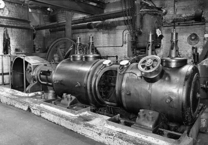
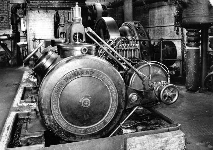
No 18581 at the Thomas Glenister Factory, High Wycombe, in April 1991. Photograph © Colin Bowden.
No 18581 is a horizontal tandem compound with cylinders of 10½" and 17" bore x 18" stroke and a 7' diameter flywheel. It has a design speed of 200 rpm and a working steam pressure of 170 psi, the engine producing approx 200/220 bhp. It was ordered on 12th February 1914 by Poppe & Co, together with a Paxman Economic boiler, 14' long x 8' diameter with a working pressure of 180 psi (Order Nos 12551 and 12552). The boiler was despatched to Isleworth on 12th June and the engine on 7th August that year. The customer is believed to have been the Poppe Rubber & Tyre Company Limited, which by 1913 occupied the "Sherland Works" site, off Sherland Road, at Richmond upon Thames. From research done by the late Graham Smart, who visited Paxman's Works to study the Company's old records, we know that the engine was originally supplied to drive rubber processing machinery through a geared arrangement and that the gears were supplied by David Bridge.
The types of Paxman-Lentz engines built at Colchester included single cylinder, coupled compound, tandem compound, coupled tandem compound and vertical compound. The tandem compound, of which No 18581 is an example, was by far the most popular type by numbers sold. Only two vertical compounds were built, one in 1907 and the other in 1909, which suggests this configuration was not very successful. Being double acting, with power strokes in both directions, Paxman-Lentz engines have four valves per cylinder, two admission on top and two exhaust underneath. The bonnets on top of the admission valves are clearly visible in the above photograph, in which the HP cylinder is on the right.
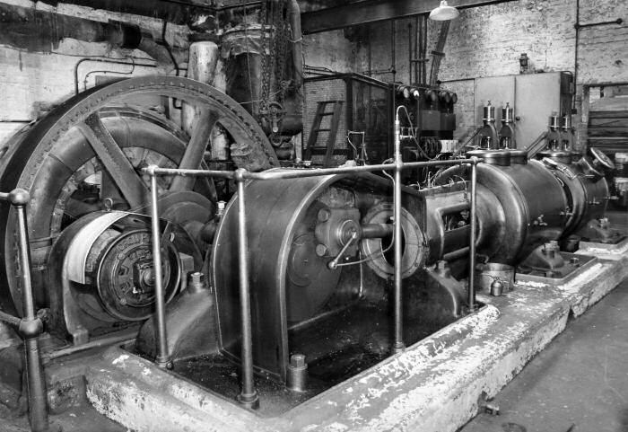
No 18581 at the Glenister factory. To the left is the flywheel, with part of the alternator visible behind it.
(April 1991) Photograph © Colin Bowden.
In 1927 No 18581 went to a furniture manufacturer, Thomas Glenister & Co of Temple Works, High Wycombe together with its original Paxman boiler. Here it was coupled to an alternator to generate power for woodworking machinery and continued in regular use until 1990. The engine then remained in situ at Glenister's factory until it was removed in 1996/97 after being purchased by Mr Richmond-Dodd of Ascot.
The Lentz engine was specifically designed to operate at high pressures, with superheated steam, and at relatively high speeds. These capabilities, and its great economy in steam consumption, constituted major selling points and marked its superiority over slide valve and piston valve types. Having the ability to perform well with high-pressure, superheated steam, nearly all Paxman-Lentz engines were built as compounds, to reap the benefits of greater efficiency and economy.
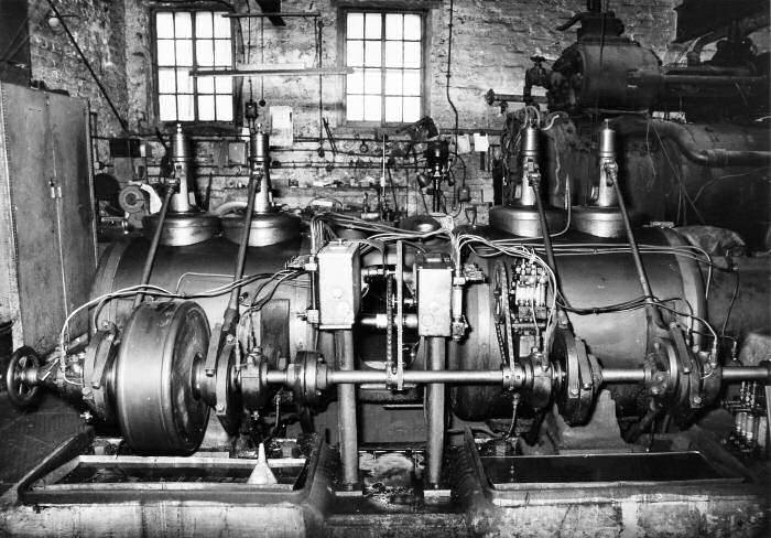
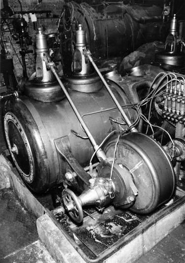
The side shaft, valve operating eccentrics, and (left front) the 'inertia' type governor.
(November 1990) Photograph © Colin Bowden.
 In the foreground of the above photograph is the side shaft which runs alongside the two cylinders. Driven from the side shaft are the eccentrics, eight in all, which operate the admission and exhaust valves. The eccentrics to the exhaust valves, underneath the cylinders, are not as visible as those to the admission valves on top. The arrangement of the eccentrics is shown in the simplified diagram shown here on the right.
In the photograph above, near the left hand end of the side shaft, is the 'inertia' type governor, in between the eccentrics to the HP cylinder valves. A more detailed view of the governor can be seen in the photograph below.
HP cylinder with steam admission valves on top (left) and Patent 'Inertia' Type Governor (right).
Photograph © Colin Bowden.
In the foreground of the above photograph, to the right, is the patent 'inertia' type governor which is mounted on the side shaft. The governor is connected to the two eccentrics which operate the valves controlling admission of steam to the HP cylinder. By moving the eccentrics, the governor varies the cut-off to suit changes in the load. The small hand-wheel at the end of the side shaft adjusts the tension of the governor spring, enabling engine speed to be varied while the engine is running.
The general arrangement of the governor and its constituent parts is shown in the drawing below.
General Arrangement drawing of the Lentz governor
The governor is directly connected to the two high-pressure steam eccentrics. These are mounted on a sliding block keyed to the side shaft and the governor controls their eccentricity, thus varying the cut-off. The governor consists of a heavy inertia ring (C), and two centrifugal weights (A) connected by a flat steel spring. The two weights (A) are fitted to the carrier fixed to the side shaft. The weights and the carrier are attached (the weights by knee joints and the carrier by a spring) to the outer ring (C) which acts like a flywheel. When the load varies, and consequently engine speed, the inertia of the outer ring, which tends to keep its speed constant, causes it to move relative to the carrier, and by moving the eccentrics alters the cut-off to suit the changing load.
Tail end view of the HP cylinder, with inertia governor and governor hand-wheel to the right. Photograph © Colin Bowden.
Paxman-Lentz engine No 18581 is believed to be in storage, in a dismantled state, in Somerset. It would be sad indeed if this very good example, one of only two known surviving Paxman-Lentz engines, was to be lost to future generations. Our earnest hope is that a proper home can be found for it, where it can be re-built, put into steam, and be accessible to the public.
Bibliography
Paxman-Lentz Steam Engines, Paxman catalogue - Publication No 723, dated May 1915.
Catalogue Illustré des Machines à Vapeur "Paxman," à Grandes Vitesses, À Distribution par Soupapes Accompagnées, Système "Lentz." Paxman-Lentz French catalogue - Publication No 204.
More about Paxman-Lentz on this website:
The page Paxman-Lentz Steam Engines has detailed descriptions of the key features of Lentz engines and full listings of orders for Paxman-Lentz engines, customers and applications and of Lentz conversions carried out by the Company on other manufacturers' engines.
During the 1920s Paxman became involved in making and marketing Lentz valves for locomotives. The history of this can be found on the page Lentz Valves for Locomotives.
Acknowledgement: My grateful thanks to Colin Bowden who granted permission to reproduce the photographs on this page. Colin has a collection of thousands of steam engine photographs he has taken over many years. He is the author of The End of a Revolution, The Last Days of Stationary Steam, Landmark Publishing 2008, an excellent technical and photographic record of many stationary steam engines during their final years.
© Richard Carr 2008
Page updated: 16 Apr 2021 at 14:06