
Paxman-Lentz Steam Engines
On this page:
An introduction to Paxman-Lentz engines
Dr Hugo Lenz
The Key Features of The Lentz Engine.
Transcript of Paxman-Lentz Steam Engines brochure of 1915 with detailed descriptions of the engines' features and tables of dimensions and power outputs.
Listing of Paxman-Lentz Engine Orders and Installations, including details of customers and applications.
Details of Conversions to Lentz Valve Gear undertaken by Paxman on other makers' engines.
Related Pages:
Paxman and Steam Engineering • Paxman-Lentz Steam Engine - No 18581 • Surviving Paxman Stationary Steam Engines • Lentz Valves for Locomotives
Browser Screen Resolution Setting: This page contains tables with relatively large numbers of columns. It is recommended that visitors use a screen resolution setting of around 1024 x 768 px or greater.
Introduction
Designed by Dr Hugo Lenz, the first Lentz engine was shown at the Como Exhibition of 1899 where it won first prize. The following year, at the Paris Exhibition, it was awarded the Grand Prix and its inventor the Gold Medal. The early application of Lentz valve gear in installations such as the City of Rome Electric Station, the International Electric Company's central station in Vienna, and the Municipal Electrical Station also in Vienna, demonstrated major fuel savings and rapidly led to its wider adoption. Lentz engines were built by a number of manufacturers in mainland Europe, notably MAN in Germany, by Davey, Paxman & Co in England, and by Erie City Iron Works, Pennsylvania in the USA.
Paxman started making Lentz engines in 1907 and built about 130 of them by the time the last was despatched in 1934. Most were horizontal tandem compound types. The others were 10 cross-coupled compounds, 2 coupled tandem compounds, 12 single cylinder engines and 2 verticals. Details of all these are given in the table of orders and installations lower down this page.
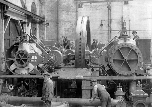
The above photograph of a large compound Paxman-Lentz in build at Colchester is dated October 1930.
The Paxman photographic archive index indicates that it is of a 500HP cross compound for 'driving a duplex
ammonia compressor with a 300 ton capacity'. It must therefore be No 23594 made for the
Lightfoot Refrigeration Co for a butter store in Auckland, New Zealand.
A major application of Paxman-Lentz engines was in the field of electrical power generation, the generators being driven directly from the crankshaft. A good number were supplied for driving refrigeration compressors which were made by Paxman for the Linde British Refrigeration Co and its successor, the Lightfoot Refrigeration Co. Others were supplied for driving machinery in mills and factories in a diverse range of industries. Details of the various applications can be found in the orders and installations table referred to above.
Surviving Paxman-Lentz Engines
Only two Paxman-Lentz engines are known to have survived. Photographs and a technical description of one, No 18581, can be found on the page Paxman-Lentz Steam Engine - No 18581. Details and a photograph of the other, No 18842, are shown on the Surviving Paxman Stationary Steam Engines page.
Dr Hugo Lenz (1859 - 1944)
Dr Hugo Lenz was born in South Africa in 1859. When he was six years old his father died and the family returned to their native Germany. Lenz trained and worked in Prussia as a naval engineer before setting up his own engine business in Vienna when he was aged 28. Later in life, during the 1920s, he is believed to have had an experimental workshop in or near Paxman's Standard Ironworks on Hythe Hill. Although there was no 't' in Lenz's surname, his engines and patents were always called 'Lentz' as this was thought easier for English-speaking people to pronounce.
Key Features of The Lentz Engine
During the latter part of the nineteenth century the use of high-pressure superheated steam was increasingly adopted for steam engines to improve their efficiency. The slide valve, which had been widely used on early steam engines, was not satisfactory for controlling superheated steam. Consequently the drop-valve, actuated by trip gear, became the conventional solution for large stationary engines. However it was not suitable for high-speed running and had another major weakness. When the trip mechanism released the valve to shut off steam to the cylinder, the valve was forced sharply onto its seat by a strong coil spring. Not only did this make it noisy but the constant shocks and hammering resulted in rapid wear to the valve and its seat. Steam tightness of the valve quickly deteriorated necessitating frequent expensive maintenance. To lessen the impact of the valve upon its seat, a dashpot was generally fitted to check its descent. This was a compromise running counter to the purpose of trip gear which was to ensure rapid closing of the valve and a quick cut-off of steam to the cylinder.
In addition to the requirement for engines to operate satisfactorily on superheated steam, the close governing of an engine's speed became an important issue in the late nineteenth century. A rapidly growing application of large steam engines was electrical power generation where it was essential to maintain a constant speed under conditions of varying load to minimise fluctuations in voltage and current.
Key features of the engine developed by Lenz were its great economy in steam consumption, due to its suitability for operating with high-pressure superheated steam, and its ability to run continuously and quietly at high piston and crankshaft speeds. These characteristics were derived from Lenz's patent valve gear, using poppet valves and positive valve gear, which provided greater control over the operation of the steam inlet valves. The engine embodied two other patents: the 'inertia' type governor, which enabled the engine to maintain a steady, constant speed under varying loads, and frictionless metallic packing. These distinctive features of the Lentz engine are described in detail in the following sections of this page and in the transcript of the 1915 Paxman-Lentz brochure below.
Lentz Valve Gear
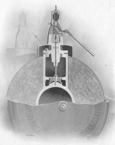
The Lentz system overcame the limitations of the drop-valve arrangement by using poppet valves, each operated by a cam lever moved by an eccentric on the governor shaft. The valve was raised by the cam acting on a roller fitted to the valve spindle at 90°. During the entire travel of the valve the roller was kept in contact with the cam by means of a light spring in the bonnet above the valve. The cleverly designed profile of the cam allowed a prompt and full opening movement. More importantly, it allowed the valve to be rapidly lowered onto its seat in a smooth controlled manner. The cam did not move clear of the roller until after the valve was seated. This 'positive valve motion' was free from shock, making the gear entirely silent even when the engine was running at the highest speeds.
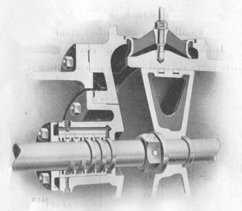
Right: Cross-sectional view of Lentz poppet valve, valve spindle and operating cam
Lentz engines were double acting, having four valves per cylinder: an admission valve on top and an exhaust valve underneath at each end of the cylinder. Lentz valve gear allowed exceptionally economical use of steam and high speeds which were not possible with trip gear. It also proved very reliable, giving long service with minimal maintenance.
The Lentz Governor
The Lentz engine was controlled by an inertia type governor mounted on the side shaft which was driven through gearing from the main crankshaft. The governor was directly connected to the two eccentrics which operated the valves on the high pressure cylinder. Extremely sensitive to variations in load, it provided excellent speed stability which was particularly important in electrical power generation applications.
Lentz Frictionless Metallic Packing
The use of high temperature superheated steam under high pressure placed greater demands not only on valve gear but also on joints around piston rods and valve spindles. Overcoming steam leakage through these joints, wear around them which accelerated leakage and the need for frequent maintenance, were major engineering challenges.
 Hugo Lenz devised a new system for piston rod packing. Unlike many other metallic packings then available for use with superheated steam, it was frictionless, free from wear, free from risks of rod heating and from the need for constant maintenance. Some other types of packing relied on springs for their tightness, but springs rapidly lost their elasticity in contact with superheated steam and required frequent renewal.
The Lentz patent packing consisted of a series of cast-iron annular distance pieces, turned and ground dead true which fitted over the piston rod, but did not touch it. In between the distance pieces were a number of square section cast-iron rings, ground to fit the piston rod exactly. The alternate rings and distance pieces formed a series of chambers or voids where any steam leaking through the joint could expand and lose pressure. (The chambers were supplied with oil under pressure and drained.) Any steam escaping from the front chamber entered the second and there expanded. A small quantity might even escape to the third chamber where it expanded further but the last ring never showing the slightest leakage.
The design of the valve spindle joint was rather simpler but based on the same principle of steam losing more of its pressure each time it expands. The valve spindle was ground to fit inside a long bush. Grooves were turned on the spindle to form a labyrinth of chambers where any steam leaking into the joint could successively expand and lose pressure sufficiently to prevent it reaching the other end of the bush.
These arrangements did away with the need for stuffing boxes and soft packing. They were effective with the highest pressure of superheated steam, showing negligible wear and preserving steam tightness indefinitely.
Paxman-Lentz Brochure of 1915 - Publication No 723
NOTE: Not all the illustrations in the original publication are reproduced in the following transcript.
No.723
Paxman-Lentz
Steam Engines.
Manufactured by
Davey, Paxman & Co., Ltd.
COLCHESTER, England.
| London Office : 78 QUEEN VICTORIA STREET, E.C. Telegraphic Address: "Paxman, Cannon, London." Telephone: City 6787 and 6788. |
Head Office & Works : COLCHESTER. Telegraphic Address: "Paxman, Colchester." Telephone: No.52. |
Codes used :
A B C (4th and 5th editions), A1, Engineering (1st and 2nd editions), Lieber's,
Moreing & Neal, and Private Codes.
MAY, 1915
Introduction.
THE Lentz type of engine was well-known, and its advantages widely recognised on the Continent for some years before we took up its manufacture. The first engine of this type was exhibited at the Paris Exhibition of 1900, where it was awarded the Grand Prix, and the Inventor the Gold Medal. Since that date, its record has been brilliant and unbroken, and up to the end of 1910, the total horse-power of engines fitted with this valve gear made and supplied was over 3,000,000.
The economy of the Lentz engine is striking, and its success was instantaneous. At the City of Rome Electric Station, the Lentz valve gear was applied to four of their existing engines. As a result, the output was increased by 25%, without any increase in the boiler power being necessary!
At the International Electric Company's central station in Vienna, nineteen cross-compound engines fitted with piston valves, totalling about 20,000 h.p., were altered to the new Lentz system between 1900 and 1903. New high-pressure cylinders were supplied to each engine, the speed increased, and new alternators supplied at a cost of some £20,000, and the whole of this outlay was recouped in one year by the resultant economy in coal consumption.
At the Municipal Electrical Station in Vienna there were installed six horizontal quadruple-expansion engines fitted with a continental type of trip-gear, the total horse-power of the engines being about 24,000. The high-pressure cylinder of each engine was converted to the Lentz system, and as a result of this change, a saving of £650 per annum was effected on each engine by the decreased coal consumption.
Results such as the foregoing need no comment. We ourselves have now been manufacturing the Lentz type of engine for several years, and during that time have put down a large number of installations, which are giving uniformly good results.
The Paxman-Lentz engine is specially designed to give the greatest economy by using high pressures and superheated steam. It is also proportioned and constructed for continuous running at a high piston speed and revolution, all parts being made suitable for working satisfactorily under these conditions.
By the adoption of this engine a large amount of power can be put down with a minimum of floor space and foundation, thus making a great reduction in initial cost in buildings, etc.
ELECTRIC GENERATING PLANT. We have supplied a large number of these engines for electrical installations, the generators being driven direct from the shaft, for which they are eminently suitable.
MILL ENGINES. The Paxman-Lentz engine is also largely used for mill driving, for which purpose we have put down a great number. Where desired the speeds may be modified to suit requirements and general conditions. The powers developed, will of course vary with any alteration in speed, the duties given in tables on pages 17, 20 and 21 are based on the normal standard speeds, for which the engines are designed.
We give below some of the factories and works at which we have put down the Lentz engines, and can arrange for intending purchasers to inspect same in operation by appointment.
| Electric Light Stations Tramway Stations Linen & Woollen Mills Engineering Works Chocolate Works Refrigerating Plants |
Flour Mills Patent Fuel Works Collieries Fan Driving Bacon Factories Chemical Works |
Timber Mills Saw Mills Rubber Works Brick Works Furniture Works |
With regard to the illustrations contained in this catalogue (not included on this page) they are all taken from engines made. It must, however, be understood that we do not bind ourselves in future engines to the exact details as shown. Modifications may be made from time to time as experience dictates.
Special Advantages offered by the Paxman-Lentz Engines.
High Speed.
Silent Running.
Extreme Economy in Steam Consumption.
Close governing by patent Inertia Governor.
Patent Metallic Packing.
No soft Packing used ; no springs.
Positive motion to Valves — no jar or hammering.
Massive design of Bed.
Forced Lubrication.
Simplicity. Elegance of Design.
Suitable for the highest temperatures of Superheated Steam.
Large Power Output, compared with Floor Space occupied.
Accessibility of Working Parts.
Guarantee:
In lieu of any warranty implied by law, we expressly guarantee to repair or replace any part which within a period not exceeding twelve months from delivery may prove to be defective through bad material or workmanship ; but the engines are supplied on the condition that we shall not be liable for any losses incurred through stoppages, nor from any direct or consequential damages arising from such defect, and subject to oil approved by us having been used for the plant. Delivery of such replacements, in the case of engines abroad, will be made f.o.b. English shipping port.
Paxman-Lentz Steam Engines.
General Design. The machining of all parts is done with the most perfect and modern tools to exact gauges and limits, so that there is no trouble in supplying spare parts. Our tools and men are quite accustomed to work to one two-thousandth part of an inch.
Frame. The frame of the engine is very substantial, and is of the Giant girder type, with a very large surface resting upon the foundations, to ensure the utmost stability. It is capable of rigidly withstanding all the working strains of the engine. It will be noticed from the small illustration at the side that there is a very large bearing surface upon the concrete foundation under the crank-pin.
Cylinder. The cylinder rests upon sole plates embedded in the foundation. The feet of the cylinder are free to slide with the varying temperature of the main castings. The piston body is machined in a special manner, so as to ensure a large bearing surface upon the bottom of the cylinder. Non-conducting composition is used for covering the cylinder body, and the whole is neatly lagged with planished sheet steel.
Crankshaft. The crankshaft is of the best forged steel, of not less than 30 tons tensile, turned and polished all over.
Main Bearing. The main bearing is cast in one piece with the bedplate. The shell of the bearing is in four parts, fitted together, and lined with anti-friction metal. To remove the bottom portion, it is simply necessary to raise the crankshaft a fraction of an inch from its bed. Both main and outer bearings are provided with chain-oiling lubrication, and the oil can be renewed while the engine is running.
Valves. There are two admission and two exhaust valves to each cylinder, which are actuated by four independent eccentrics operated by the side shaft. This side shaft is driven by the conical surface shown at "A," and is really a friction drive pure and simple, the purpose of the bevel gearing being merely to ensure the correct setting of the valves being preserved ; the drive is therefore perfectly noiseless.
It will be noticed from the design in the next figure that these valves are free to lift easily in the case of any abnormal pressure arising within the cylinder, and each admission valve therefore also serves the purpose of a relief valve. Great care is taken in their design, and they are of such a form that even should distortion take place under excessive heat, this in no way affects the tightness of the valve, neither does it interfere with its easy working.
 Valve Gear. This very novel and important detail of the Paxman-Lentz engine is shown in section by the illustration overleaf (see right). There are no stuffing boxes to the valve spindles, which are ground to fit the long bushes shown. Grooves are turned on the spindles to form a labyrinth packing, from which there is no leakage. The usual soft packing, with its attendant troubles and constant leakage, is thus done away with.
With the Paxman-Lentz valve gear, no dash-pot is used. The valve is raised by the cam lever "A," acting upon the roller "B," this lever being moved by the eccentric, and the whole movement is accomplished without noise or hammering. The roller "B" is always kept in close contact with the cam or lever "A" during the travel of the valve, by means of the spring shown in the bonnet. The cam does not move clear of the roller until after the valve is seated, and consequently, even when the engine is running at the highest speeds, the gear is entirely silent. In the Paxman-Lentz engines, the friction to which the valve is exposed is to all intents and purposes nil. The advantages of this system will be immediately recognised by the most casual observer, however slight his experience of valve gears.
In the case of a drop-valve engine actuated by trip-gear, the valve is suddenly released by the tripping action of the mechanism, and the valve is forced sharply upon its seat by the pressure of a strong coil spring. In order to diminish the damaging effect upon the valve and seat occasioned by this hammering action, its descent is checked by means of a dash-pot, and in precisely as much as the dash-pot is used, so the trip-gear fails in its original intention, which is to ensure the rapid closing of the steam admission valves. The whole complicated system is thus a compromise between, on the one hand, a sharp and clean cut-off obtained by the valve being hammered down violently upon its seat by the pressure of the spring, and, on the other hand, a gradual cut-off obtained by means of the retarding action of the dash-pot. With the Paxman-Lentz positive valve gear, on the contrary, there is no tripping movement, but the valve is lowered gently on to its seat by means of the cam (the profile of which is so shaped as to allow this to be done rapidly), and when the valve is seated, and not until then, the cam moves clear of the roller. This system renders quite permissible the employment of such high piston speeds and revolutions (even in the case of very large engines) as would be unattainable and quite out of the question with trip-gear.
We give on next page a diagram (omitted on this page) comparing the Paxman-Lentz positive valve gear with the ordinary trip gear, from which the striking simplicity and superiority of our gear is at once apparent.
Lubrication. All the parts subject to wear are efficiently lubricated; and forced lubrication, by means of a patent mechanically-driven oil pump of the sight-feed type, is provided for the valve chests, packing, and pistons. Oil trays are fitted wherever necessary, to prevent any possibility of the oil reaching the foundations.
Governor. The governor is another patented detail in connection with these engines, and is extremely sensitive to the slightest variation in the load. It is of the "inertia" type, mounted on the side shaft, and directly connected to the two high-pressure steam eccentrics ; these eccentrics are mounted on a sliding block keyed to the shaft, the governor controlling their eccentricity, and consequently varying the cut-off. The governor is shown in section below.
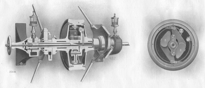
It consists of a heavy inertia ring "A," and two centrifugal weights "B" connected by a flat steel spring, which can be removed and replaced in a few minutes. The two weights "B B" are fitted to the carrier "C" fixed to the side shaft, the weights and the carrier being attached to the outer ring "A" (in the case of the weights by knee joints formed by "D" and "E," and in the case of the carrier by a spring) which performs the action of a flywheel. When the least variation of load, and consequently of speed, takes place, the inertia of the outer ring which tends to keep its speed constant, causes it to move relatively to the carrier, and by moving the eccentrics alters the cut-off to suit the changing load.
The governor regulates within an exceptionally short period, and the momentary change of speed due to the load being thrown on or off is only slightly in excess of the permanent change. Below, is given a speed diagram (omitted on this page) showing graphically the very slight alteration in speed occasioned by throwing the load suddenly off or on the engine, the resultant change of speed being hardly perceptible. The action of the Paxman-Lentz governor is immediate, and it combines extreme sensibility with a perfect stability only comparable with the best turbines.
A hand-wheel is provided at the end of the side shaft, to enable the speed of the engine to be altered while running, by adjusting the tension of the governor spring.
 Packing. The piston-rod packing is made on the Lentz patent system. By eliminating springs, friction is reduced to a minimum, and as the packing is free from wear perfect steam-tightness is assured. The packing is shown in detail below (see right). It consists of a series of cast-iron annular distance pieces, turned and ground dead true. These annular distance pieces fit over the piston-rod, but do not touch it, whilst between the chambers are a number of square-section cast-iron rings, ground to fit the piston-rod exactly, forming with the distance pieces a series of chambers which are supplied with oil under pressure, and efficiently drained. Any steam escaping from the front chamber enters the second chamber, and there expands ; a small quantity may even escape to the third chamber, where it would undergo a further expansion, and so on ; but the last ring will never show the slightest leakage.
Many metallic packings which have been put on the market for use with superheated steam, owing to their construction, are more or less defective, because wherever there is friction there is wear, liability of the rod heating, useless work, and consequent constant attention. Packings which depend for tightness upon springs are subject to yet a further drawback, in that springs lose their elasticity rapidly in contact with superheated steam, and require frequent renewal.
Superheat. The Paxman-Lentz engine is specially suitable for use with the highest temperature of superheated steam. All valve and cylinder cover joints are made metal-to-metal, no soft packing of any kind being used, either for the stop valve, or any other part of the engine whatsoever.
Steam Consumption. The economy in steam consumption which is obtainable with engines of the Lentz type is unequalled by any other steam engine at present on the market, and the details given on page 3 of the Introduction are conclusive evidence as to this statement. The following figures are the results of some tests carried out on our engines :—
| Duty of Engine. (i.h.p.) | Pressure at Engine Stop Valve. (lbs.) | Added Superheat. (Fahrenheit) | Vacuum. | Steam per i.h.p. per hour. | |
|---|---|---|---|---|---|
| Superheated. | Saturated. | ||||
| 366 | 170 | 150° | 26½" | I0.4 lb. | 12.3 lb. |
| 300 | 140 | 150° | 27" | 10.35 lb. | |
| 600 | 170 | 100° | 25" | 10.91 lb. | |
| 600 | 170 | 150° | 25" | 10.59 lb. | |
| 570 | 150 | 175° | 27½" | 10.34 lb. | |
| 425 | 170 | 150° | Non Condg. | 13.45 lb. | |
| 215 | 170 | 150° | Non Condg. | 14.0 lb. | |
| 537 | 168 | 175° | 24.25" | 10.38 lb. | |
| 200 | 170 | none | 26" | — | 13.25 lb. |
| 250 | 150 | 150° | 25" | 10.44 lb. | |
The first results mentioned above were obtained from a 27½" stroke engine, within two days of first running it, and an overload of 33.33 per cent. was easily obtained.
The results mentioned on the second line of the above table were from the tandem compound engine illustrated on page 24, when tested after working 10 months continuously in a flour mill ; the other results were obtained from engines driving Electric Generators direct coupled.
From these examples, it will be seen that even with a moderate steam pressure, the Paxman-Lentz engine is extremely economical, and this economy is maintained under actual working conditions.
Condensers. Wherever possible the adoption of a condenser is strongly recommended, as by this means an economy of at least 15 per cent. is obtained. The condensing apparatus itself can be placed in various positions with reference to the engine, to suit the space available, water level, and other local conditions. The type of air pump we employ embodies several original features, which have proved highly satisfactory in practice. The valves themselves consist of annular metallic rings, having a very small lift, and these give adequate area for the passage of the condensed steam and water ; and by reason of their small lift and weight are capable of working with the engines at the speeds listed in this catalogue. The air-pump piston is of the trunk type, and is made of gunmetal.
It is very often the case that air pumps and condensers do not receive the same care and attention either in design or construction, as practice has shown to be necessary for such adjuncts ; but upon our condensers the same scrupulous care is bestowed as is given to all parts of the engine, and the important questions of access and easy renewal have been most carefully kept in view.
| Duties and Sizes of The Paxman-Lentz Single-Cylinder Engines | |||||||||||
|---|---|---|---|---|---|---|---|---|---|---|---|
| Cylinder | Flywheel * | Indicated Horse Power | |||||||||
| Dia. (in.) | Stroke (in.) | Dia. | Rev per Minute | Non-Condensing | Condensing | ||||||
| 80 lbs. | 140 lbs. | 80 lbs. | 140 lbs. | ||||||||
| Norm. | Max. | Norm. | Max. | Norm. | Max. | Norm. | Max. | ||||
| 13 | 24 | 8' 0" | 190 | 104 | 146 | 130 | 210 | 99 | 150 | 128 | 217 |
| 14 | 24 | 8' 0" | 190 | 122 | 170 | 154 | 248 | 116 | 177 | 150 | 255 |
| 15¼ | 27½ | 9' 0" | 170 | 157 | 218 | 197 | 318 | 149 | 227 | 193 | 328 |
| 16 | 27½ | 9' 0" | 170 | 164 | 227 | 205 | 332 | 155 | 237 | 200 | 342 |
| 16¾ | 30 | 9' 6" | 155 | 176 | 246 | 222 | 358 | 168 | 256 | 217 | 368 |
| 17¾ | 30 | 9' 6" | 155 | 202 | 288 | 252 | 405 | 190 | 290 | 246 | 419 |
| 19 | 33½ | 11' 0" | 145 | 239 | 333 | 300 | 486 | 227 | 346 | 293 | 500 |
| 20 | 33½ | 11' 0" | 145 | 266 | 370 | 333 | 540 | 252 | 384 | 326 | 555 |
| 20½ | 36 | 12' 0" | 135 | 280 | 390 | 350 | 568 | 266 | 405 | 344 | 565 |
| 21½ | 36 | 12' 0" | 135 | 310 | 430 | 387 | 628 | 293 | 448 | 380 | 646 |
| 22½ | 42 | 13' 6" | 115 | 333 | 463 | 417 | 676 | 315 | 482 | 408 | 695 |
| 23½ | 42 | 13' 6" | 115 | 365 | 507 | 456 | 740 | 345 | 527 | 446 | 760 |
| 24½ | 48 | 15' 0" | 100 | 394 | 547 | 493 | 798 | 373 | 568 | 482 | 820 |
| 25½ | 48 | 15' 0" | 100 | 428 | 595 | 535 | 865 | 405 | 618 | 524 | 892 |
| 28 | 54 | 16' 0" | 90 | 521 | 734 | 650 | 1055 | 492 | 753 | 638 | 1086 |
| 29 | 54 | 16' 0" | 90 | 561 | 780 | 700 | 1135 | 530 | 810 | 687 | 1170 |
NOTES relating to Single-Cylinder Engines table above:
The catalogue shows IHPs for steam pressures of 80, 90, 100, 120 and 140 lbs per square inch. In the table above the IHPs for steam pressures of 90, 100 and 120 psi have been omitted.
* The catalogue does not give the weights of flywheels, saying only that these will be "According to requirements".
| Duties and Sizes of The Paxman-Lentz Compound Tandem & Coupled Engines | ||||||||||||
|---|---|---|---|---|---|---|---|---|---|---|---|---|
| Cylinders | Flywheel * | Indicated Horse Power | ||||||||||
| Dia. (in.) | Stroke (in.) | Dia. | Rev per Minute | Non-Condensing | Condensing | |||||||
| High Press | Low Press | 100 lbs. | 170 lbs. | 100 lbs. | 170 lbs. | |||||||
| Norm. | Max. | Norm. | Max. | Norm. | Max. | Norm. | Max. | |||||
| 9 | 15½ | 18 | 7' 6" | 210 | 105 | 115 | 155 | 175 | 120 | 132 | 148 | 166 |
| 10½ | 17 | 18 | 7' 6" | 210 | 126 | 137 | 190 | 210 | 145 | 160 | 180 | 200 |
| 11¼ | 18½ | 21 | 7' 6" | 200 | 166 | 180 | 250 | 277 | 190 | 210 | 235 | 260 |
| 12 | 20 | 21 | 7' 6" | 200 | 195 | 210 | 290 | 325 | 220 | 245 | 275 | 305 |
| 13 | 21½ | 24 | 8' 0" | 190 | 245 | 265 | 365 | 410 | 277 | 310 | 345 | 385 |
| 14 | 23 | 24 | 8' 0" | 190 | 280 | 305 | 420 | 470 | 315 | 350 | 395 | 440 |
| 15¼ | 25 | 27½ | 9' 0" | 170 | 340 | 370 | 510 | 565 | 380 | 425 | 480 | 530 |
| 16 | 26½ | 27½ | 9' 0" | 170 | 380 | 417 | 575 | 635 | 430 | 480 | 540 | 600 |
| 16¾ | 27¾ | 30 | 9' 6" | 155 | 415 | 455 | 620 | 685 | 470 | 525 | 590 | 655 |
| 17¾ | 29¼ | 30 | 9' 6" | 155 | 460 | 500 | 690 | 760 | 525 | 585 | 655 | 725 |
| 19 | 31¼ | 33½ | 11' 0" | 145 | 550 | 595 | 825 | 910 | 625 | 700 | 780 | 870 |
| 20 | 32¾ | 33½ | 11' 0" | 145 | 605 | 655 | 900 | 1000 | 685 | 765 | 855 | 950 |
| 20½ | 34 | 36 | 12' 0" | 135 | 650 | 710 | 975 | 1080 | 740 | 825 | 925 | 1030 |
| 21½ | 35½ | 36 | 12' 0" | 135 | 710 | 775 | 1075 | 1175 | 805 | 900 | 1010 | 1120 |
| 22½ | 37½ | 42 | 13' 6" | 115 | 785 | 860 | 1190 | 1300 | 900 | 1000 | 1120 | 1240 |
| 23½ | 39 | 42 | 13' 6" | 115 | 850 | 930 | 1290 | 1400 | 975 | 1080 | 1210 | 1340 |
| 24½ | 41 | 48 | 15' 0" | 100 | 930 | 1020 | 1420 | 1560 | 1070 | 1185 | 1330 | 1475 |
| 25½ | 43 | 48 | 15' 0" | 100 | 1025 | 1125 | 1560 | 1700 | 1175 | 1300 | 1460 | 1620 |
| 28 | 46 | 54 | 16' 0" | 90 | 1190 | 1300 | 1800 | 1970 | 1380 | 1500 | 1700 | 1880 |
| 29 | 48 | 54 | 16' 0" | 90 | 1300 | 1420 | 1970 | 2140 | 1470 | 1650 | 1850 | 2050 |
NOTES relating to Compound Engines table above:
The 18" and 21" stroke sizes were not made as Coupled Engines.
The catalogue shows IHPs for steam pressures of 100, 110, 120, 130, 140, 150, 160 and 170 lbs per square inch. In the table above the IHPs for steam pressures of 110, 120, 130, 140, 150 and 160 psi have been omitted.
* The catalogue does not give the weights of flywheels, saying only that these will be "According to requirements".
Paxman-Lentz Engine Orders and Installations
Details of the orders, customers and applications of the approximately 130 Paxman-Lentz engines built at Colchester are given in the table below. The information in this, and the subsequent table of Lentz conversions, is almost entirely the work of the late Graham Smart of Stourbridge, West Midlands. Graham spent a considerable amount of time at Colchester researching Paxman's Lentz engines and it is good to make the fruit of his considerable labours more widely available.
Abbreviations used in the table below:
HTC = Horizontal Tandem Compound VC = Vertical Compound SC = Single Cylinder
CC = Cross Compound Engine CT = Coupled Tandem SLV = Special Locomotive Valves
LH = left hand; RH = right hand; S/H = Second hand
| Order Date | Order No | Engine No | Engine Details | Customer | Engine Duty | Date Sent | Drwg Ref. |
|---|---|---|---|---|---|---|---|
| 27-02-06 | 7871 | 12874 | HTC 300 IHP 19" & 31½" x 33½" LH | E Marriage & Son Felixstowe Dock Suffolk | Rope drive to drive flour mill. 16 ropes. (see Note 1 for more on this installation. | 10-04-07 | |
| 23-05-06 | 7984 | 3 engs | HTC 800 IHP 20" & 32¾" x 33½" LH | Crompton & Co for Madras, India | Crankshaft generator - 500kW per engine. For power station. | 10-09-07 | |
| 23-05-06 | 7985 | 2 engs | HTC 400 IHP 14½" & 24½" x 27½" LH | Crompton & Co for Madras, India | Crankshaft generator - 250kW per engine. For power station. | ? | |
| 23-05-06 | 7986 | 2 engs | HTC 800 IHP 20" & 32¾" x 33½" | Crompton & Co for Madras, India | Crankshaft generator - 500kW per engine. For power station. | 20-03-08 | |
| 23-05-06 | 7987 | 2 engs | HTC 400 IHP 14½" & 24½" x 27½" | Crompton & Co for Madras, India | Crankshaft generator - 250kW per engine. For power station. | 13-05-08 | |
| 14-09-06 | 8102 | ? | VC 150 rpm 875 bhp 27" & 47" x 20" | Electrical Construction Co, Wolverhampton for City & S London Rly | Direct coupled to two 300kw DC dynamos (in tandem). Stockwell Power Station, London | 24-10-07 | |
| 21-10-07 | 8604 | 14584 | CC 100 rpm 400 bhp 19" & 31¼" x 33½" | Strain & Robertson, Glasgow for Officina Maria, Iquique, Chile | Rope drive to Siemens-Schuckert Alternator. 525V at 375 rpm. | 08-09-08 | |
| 14-07-08 | 8846 | ? | VC 140 rpm 5½" & 9" x 7" | City & Guilds of London Inst Finsbury Technical College | Laboratory Test Engine (by 1932 at University College, Gower Street, London.) Paxman microfilm records show this order was for "2 x vertical single crank double acting high speed open type … to be arranged so that they can be connected together by a coupling shaft when required to run as a compound engine." The HP cylinder to be 5½" x 7" and the LP to be 9" x 7", to run at 400rpm. The drawings were to be approved by Prof Coker. Paxman was also to supply 'test bars' 3" square by 6 foot long "for experiments in conductivity such as described in proceedings of Institute of Civil Engineers Vol 131 - 1891-8 on the law of condensation of steam, etc." The test bars were made of cylinder metal and also the liner metal. The instructions were that the cylinder material test bars were to be cast at the same time as the cylinders and covers. | 20-09-09 | |
| 12-08-08 | 8880 | 14873 | HTC 140 rpm 150 bhp 11¼" & 18½" x 20" | Davidson & Co, Sirocco Works, Belfast for Shipley Colliery | Direct coupled to colliery ventilation fan. | 10-03-09 | 2009/2A |
| 14-06-09 | 9148 | 15170 | HTC 57 rpm 205 bhp 16¾" & 27¾" x 30" | Linde British Refrigeration for Canning Town, London | Direct coupled to 15½" x 30" ammonia compressor on LH side of engine. | 29-09-09 | |
| 21-06-09 | 9165 | 15190 | CC 180 rpm 300kW 16" & 26½" x 27½" | Thos F Craddock Esq, Leadenhall St, London EC for Calcutta, India | Crankshaft generator. Dick Kerr dynamo - 300kW. | 13-12-09 | |
| 21-09-09 | 9227 | 15256 | HTC 170 rpm 400 bhp 16" & 26½" x 27½" | Cwmaman Colliery Co Ltd Aberaman, South Wales | Direct coupled to colliery ventilation fan (Sirocco). | 05-08-10 | |
| 25-11-09 | 9273 | 15301 | HTC 57 rpm 205 bhp 16¾" & 27¾" x 30" | Linde British Refrigeration Co for St Petersburg, Russia | Direct coupled to 15½" x 30" ammonia compressor on LH side of engine. (Repeat of O/No 9148) | 13-04-10 | |
| 07-02-10 | 9329 | 15358 | HTC 120 rpm 300 IHP 16" & 26½" x 27½" LH | J S Fry & Sons Ltd, Wapping, Bristol S/H in 1932 to McCall Brothers (woollen cloth manufacturers), Victoria Mills, Trowbridge | 12' dia. flywheel grooved for 7 x 2" diameter ropes. At Trowbridge, drive from flywheel by 5 vee belts to Bruce Peebles & Co alternator, 500kVA, 440 volts, 656 amps. Superheated. Steam pressure 160 psi. Surface condenser. Engine stopped on 28 June 1961 and scrapped in June 1974. | 12-05-10 | |
| 04-04-10 | 9365 | 15394 | HTC 80 rpm 19" & 31¼" x 33½" RH | Stoate & Son, Somerset (sold 8/25 via Geo Cohen & Sons) | Rope drive to factory | 23076 | |
| 13-04-10 | 9428 | 15456 | HTC 900 IHP 19" & 31¼" x 33½" RH | AEG Electrical Co for Uruguay | Crankshaft generator (Power station) | 03-10-10 | |
| 13-04-10 | 9429 | 15457 | HTC 900 IHP 19" & 31¼" x 33½" RH | AEG Electrical Co for Uruguay | Crankshaft generator (Power station) | 01-11-10 | |
| 13-04-10 | 9430 | 15458 | HTC 450 IHP 14" & 23" x 24" RH | AEG Electrical Co for Uruguay | Crankshaft generator (Power station) | 01-11-10 | |
| 13-04-10 | 9431 | 15459 | HTC 450 IHP 14" & 23" x 24" | AEG Electrical Co for Uruguay | Crankshaft generator (Power station) | 18-11-10 | |
| 03-09-10 | 9620 | 15648 | HTC 12" & 20" x 21" RH | Chas & Thos Harris Calne, Wiltshire | Crankshaft generator (Bacon factory) | ||
| 20-02-11 | 10865 | 16893 | HTC 180 rpm 619 IHP 16" & 26½" x 27½" LH | Powell Duffryn Coal Co for Penallta Colliery, South Wales | Direct coupled to colliery ventilation fan via Croft & Perkins coupling. | ||
| 25-02-11 | 10876 | 16904 | HTC 135 rpm 500 bhp 17¾" & 29¼" x 30" | Bedwas Navigation Colliery Co Bedwas, South Wales | Direct coupled to colliery ventilation fan via Hele-Shaw friction clutch. | ||
| 05-04-11 | 10967 | HTC 16" & 26½" x 27½" | Bath & West Counties Show held Cardiff 31/5 to 5/6 (Engine built to O/No 10865 used - minus flywheel) | 22-05-11 | |||
| 17-08-11 | 11153 | HTC 120 rpm 275 bhp 16" & 26½" x 27½" | Union Cold Storage Co for Riga, Russia | Rope drive (to ammonia compressor?) 14 x 1½" dia ropes. | |||
| 25-09-11 | 11231 | 17259 | HTC 170 rpm 375kW 16" & 26½" x 27½" | Apperley & Curtis | Crankshaft alternator (Siemens) | 15-05-12 | 23015 23090 |
| 27-09-11 | 11237 | 17265 | HTC 160 rpm 120kW 12" & 20" x 21" | Vestey Brothers for Albert Dock, Liverpool | Crankshaft mounted DC dynamo (Crompton). | 04-01-12 | 23012 |
| 14-05-12 | 11628 | 17657 | HTC 185 rpm 160/170 bhp 12" & 20" x 21" | Raymond Allen Ltd, Cirencester S/H to Samuel Salter, Homemill, Trowbridge | Rope drive to factory 8 x 1½" dia ropes | 31-08-12 | |
| 25-05-12 | 11639 | 17668 | HTC 147 rpm 180 IHP 12" & 20" x 21" | Plymouth Co-operative Flour Mills S/H to Vestey Bros - see O/N 13141 | Rope drive to flour mill 6 x 1¾" diameter ropes | 28-09-12 | 23379 23448 |
| 04-06-12 | 11671 | 17701 | HTC 135 rpm 230-265 IHP 14" & 23" x 24" | Henry Workman Ltd Woodchester Sawmills, Stroud, Glos | Rope drive to sawmill 10 x 1½" dia ropes | 07-02-13 | 23523 |
| 15-07-12 | 11738 | 17768 | HTC 175 rpm 170 IHP 12" & 20" x 21" | Welch Margetson & Co London | Rope drive | 07-05-13 | |
| 08-07-12 | 11743 | 17773 | HTC 170 rpm 220-270 IHP 12" & 20" x 21" | Woodworkers Co Chalford, Glos. | Rope drive 8 x 1½" dia ropes | 01-02-13 | |
| 15-07-12 | 11746 | 17776 | HTC 200 rpm 247-320 IHP 12" & 20" x 21" | E Sherry Homerton, London. (HP cyl of this engine exhib at Royal Show, Bristol, Jul 1913. O/No 12220) | Crankshaft generator and rope drive from flywheel 6 x 1.3/8" dia ropes | 05-12-13 | 23671 |
| 25-07-12 | 11751 | 17781 | HTC 100/115 rpm 220-300 IHP 16" & 26½" x 24" | Powell Duffryn Coal Co for Fforchaman Colliery, South Wales | Direct coupled to colliery ventilation fan via Zodel-Voith flexible coupling. | 19-03-13 | |
| 25-07-12 | 11752 | 17782 | HTC 100/115 rpm 220-300 IHP 16" & 26½" x 27½" | Powell Duffryn Coal Co for Aberaman Colliery, South Wales | Direct coupled to colliery ventilation fan via Zodel-Voith flexible coupling. | 08-04-13 | |
| 31-08-12 | 11842 | 17872 | HTC 134 rpm 247-330 IHP 16" & 26½" x 27½" | Powell Duffryn Coal Co for Cwm Neol Colliery, Aberdare, S Wales | Driving colliery ventilation fan by ropes from flywheel 12 x 1½" dia ropes | 27-06-13 | |
| 04-11-12 | 11939 | 17969 | HTC 60 rpm 264 bhp 20" & 32¾" x 33½" (Standard 30" str bed used) | Linde British Refrigeration Co for Vestey Brothers | Direct coupled to 18½" x 36" ammonia compressor - driven from outer end of crankshaft. | 27-02-13 | |
| 04-11-12 | 11940 | 17970 | HTC 57 rpm 230 bhp 19" & 31½" x 33½" | Linde British Refrigeration Co for Vestey Brothers | Direct coupled to 15½" x 30" ammonia compressor - driven from outer end of crankshaft. | 15-05-13 | |
| 04-11-12 | 11941 | 17971 | HTC 57 rpm 130 bhp 15¼" & 25" x 27½" | Linde British Refrigeration Co for Vestey Brothers | Direct coupled to 15½" x 30" ammonia compressor - driven from outer end of crankshaft. | 15-05-13 | |
| 04-11-12 | 11942 | 17972 | HTC 57 rpm 230 bhp 19" & 31½" x 33½" | Linde British Refrigeration Co for Vestey Brothers | Repeat of Order No 11940 | 07-11-13 | |
| 04-11-12 | 11943 | 17973 | HTC 57 rpm 130 bhp 15¼" & 25" x 27½" | Linde British Refrigeration Co for Vestey Brothers | Repeat of Order No 11941 | 07-11-13 | |
| 04-11-12 | 11944 | 17974 | HTC 78 rpm 140 bhp 14" & 23" x 24" | Linde British Refrigeration Co for Vestey Brothers, sent to Battersea | Direct coupled to 13½" x 24½" ammonia compressor - driven from outer end of crankshaft. | 24-02-13 | |
| 06-01-13 | 12024 | 18054 | CC 150 rpm 350kW 17¾" & 29¼" x 30" | Buxton, Cassina & Cie for Pelotas, Argentina (Pelotas Tramways & Lighting) | Driving crankshaft DC generator (BT-H) for town tramways and lighting | 03-02-14 | 23876 23950 |
| 06-01-13 | 12025 | 18055 | CC 150 rpm 350kW 17¾" & 29¼" x 30" | As above | As above | 12-02-14 | 23876 23950 |
| 03-02-13 | 12086 | 18116 | HTC 170 rpm 450 bhp 16" & 26½" x 27½" | Ffaldau Collieries Co Pontycymmer, S Wales | Direct coupled to 176" diameter mine ventilation fan. | 19-09-13 | 23822 23834 |
| 27-03-13 | 12143 | 18173 | HTC 145 rpm 700 bhp 20" & 32¾" x 33½" | Davidson & Co, Belfast for Great Western Colliery Co, Cwm Colliery, Pontypridd | Direct coupled to "Sirocco" mine ventilation fan. | 05-03-14 | 23922 |
| 15-04-13 | 12180 | 18210 | HTC 210 rpm 100kW (148 bhp) 10½" & 17" x 18" | John Barker & Co Ltd Kensington, London (S/H to Welch Margetson & Co. 15-7-25) | Driving crankshaft generator - electricity supply for department store. | 22-11-13 | 24112 |
| 15-04-13 | 12181 | 18211 | HTC 190 rpm 250kW (362 bhp) 14" & 23" x 24" | John Barker - as above (S/H to Union Cold Storage, Rockhampton, in 1925) | Driving crankshaft generator - electricity supply for department store. | 22-10-13 | 24112 |
| 15-04-13 | 12182 | 18212 | HTC 190 rpm 250kW (362 bhp) 14" & 23" x 24" | John Barker - as above (S/H to Gomme, High Wycombe, Sept 1926) | As above. (Order Nos 12180-12182 situated in basement of store.) | 06-11-13 | 24112 |
| 01-05-13 | 12225 | 18255 | HTC 115 rpm 120 bhp 12" & 20" x 21" | F Skurray & Son Town Flour Mills, Swindon, Wilts. | Driving flour mill by ropes. Flywheel grooved for 10 x 1¼" dia ropes. | 04-09-13 | |
| 09-12-13 | 12502 | HTC 16" & 26½" x 27½" (Stock Order No 666) | for Universal (1914) Exhibition Nottingham | Order cancelled.. | |||
| 29-12-13 | 12528 | 18558 | HTC 170 rpm 350 IHP 16" & 26½" x 27½" | Sussex Brick & Estates Ltd Sussex | Driving brickworks by ropes. Flywheel grooved for 10 x 1½" dia ropes. | 17-02-14 | 24364 |
| 26-01-14 | 12547 | 18577 | HTC 150 rpm 500 bhp 17¾" & 29¼" x 30" | J M V Money Kent for Cape Copper Co, Calcutta. (Later to Chasnalla Colliery, India) | Driving crankshaft generator (by Phoenix Dynamo Mfg Co, Bradford. 3-phase alternator - 300V) | 19-01-15 | |
| 26-01-14 | 12548 | 18578 | HTC 150 rpm 500 bhp 17¾" & 29¼" x 30" | As above | As above | 19-01-15 | |
| 12-02-14 | 12551 | 18581 | HTC 200 rpm 10½" & 17" x 18" | Poppe & Co Isleworth, Mddx (Second hand to Thomas Glenister & Co, furniture manufacturers, Temple Works, High Wycombe, in 1927) | Driving rubber processing machinery by gears (gears supplied by David Bridge). At High Wycombe: steam pressure 170 psi; speed 212 rpm; output 220 bhp; 7' dia. flywheel; duty: driving an alternator. Engine stopped 1990 and removed 1996/7. more > | 07-08-14 | |
| 24-04-14 | 12690 | 18720 | HTC 170 rpm 300kW (437 bhp) 16" & 26½" x 27½" | Douglas Brothers Bristol | Driving crankshaft generator - Crompton DC machine - 330kW at 220V. | 15-06-14 | 24540 25372 |
| 27-05-14 | 12733 | Not built | HTC 165 rpm 225 IHP 12" & 20" x 21" | Golden Valley Ochre Co Ltd Bristol | Driving factory by ropes Flywheel grooved for 8 x 1" dia ropes. (Order transferred to O/No 12835) | ||
| 22-06-14 | 12767 | 18797 | HTC 60 rpm 250 bhp 20" & 35" x 33½" | Vestey Brothers for Manchuria (Engine built to O/No 12771 used for this order) | Direct coupled to 15½" x 30" ammonia compressor - 150 bhp. 100 bhp by belt from flywheel | 22-04-15 | |
| 22-06-14 | 12769 | 18799 | HTC 60 rpm 150 bhp 16" & 30" x 27½" | Vestey Brothers for Port Darwin, Australia | Direct coupled to 15½" x 30" ammonia compressor | 03-06-15 | |
| 22-06-14 | 12771 | 18801 | HTC 60 rpm 250 bhp 20" & 35" x 33½" | Vestey Brothers for Nanking, China | Direct coupled to 15½" x 30" ammonia compressor - 150 bhp. 100 bhp by belt from flywheel | 14-12-15 | |
| 22-06-14 | 12773 | 18803 | HTC 60 rpm 150 bhp 16" & 30" x 27½" | Vestey Brothers for Auckland, New Zealand | Direct coupled to 15½" x 30" ammonia compressor | 28-09-15 | |
| 30-06-14 | 12797 | 18827 | HTC 200 rpm 220 bhp 12" & 20" x 21" | Avon Rubber Co Melksham, Wilts | Driving by ropes Flywheel grooved for 6 x 1½" dia ropes | 30-07-15 | |
| 15-07-14 | 12806 | 18836 | HTC 155 rpm 600 bhp 16¾" & 29¼" x 30" | Theodore Kipp & Co Winnipeg, Canada | Driving flour mill by ropes Flywheel grooved for 14 x 1½" dia ropes plus 175kW c/shaft generator | 04-12-14 | 24838 |
| 22-07-14 | 12812 | 18842 | CC 155 rpm 570 IHP 17¾" & 29¼" x 30" | Denny Mott & Dickson for Bangkok (still at work mid-1990) | Driving teak sawmill by ropes Flywheel grooved for 17 x 1¼" dia ropes As at 2009 this engine still exists in Bangkok. | 23-02-15 | 24790 |
| 12-08-14 | 12835 | 18865 | HTC 120 rpm 210/250 bhp 14" & 23" x 24" | Golden Valley Ochre Co Ltd Bristol | Driving factory by ropes Flywheel grooved for 6 x 2" dia ropes. | 09-12-14 | 24823 |
| 14-08-14 | 12839 | 18869 | HTC 140 rpm 550 bhp 17¾" & 29¼" x 30" | Saxby & Farmer Ltd Chippenham, Wilts. | Driving factory by ropes Flywheel grooved for 12 x 1¼" dia ropes. Plus crankshaft generator - 220kW Crompton | 24-04-15 | 24908 |
| 17-08-14 | 12843 | 18873 | HTC 135 rpm 20" & 32¾" x 33½" | Lusty & Sons Bromley-by-Bow, London | Driving woodworking machines by ropes Two flywheels grooved for 9 x 1¾" dia ropes and 7 x 2" dia ropes. | ??-05-15 | 25365 |
| 05-08-14 | 12845 | 18875 | HTC 175 rpm 435 IHP 15¼" & 25" x 27½" | Chesham Electric Light & Power Co Chesham, Bucks. | Driving ECC generator by extension of crankshaft | 04-05-15 | 24906 |
| 16-10-14 | 12872 | 18902 | HTC 60 rpm 20" & 35" x 33½" | Vestey Brothers for Madagascar | Driving ammonia compressor (Engine built to O/No 12767 used for this order) | 17-11-14 | |
| 16-11-14 | 12887 | 18917 | HTC 60 rpm 150 bhp 16" & 30" x 27½" | Vestey Brothers for Whangarei, New Zealand | Driving ammonia compressor (Engine built to O/No 12769 used for this order) | 29-12-14 | |
| 15-04-15 | 12974 | 19004 | HTC 60 rpm 150 bhp 16" & 30" x 27½" | Vestey Brothers for Auckland, New Zealand - with O/No 12773 (identical unit) (but order book says sent to Nanking) | Direct coupled to 15½" x 30" ammonia compressor | ||
| 26-05-15 | 13015 | 19045 | HTC 130 rpm 375/475 IHP 16" & 26½" x 27½" | Redlers Limited Gloucester | Rope drive to factory 16 x 1½" dia ropes | 11-02-16 | 25327 |
| 08-06-15 | 13022 | 19052 | HTC 60 rpm 150 bhp 16" & 30" x 27½" | Vestey Brothers for Harbin, China | Direct coupled to 15½" x 30" ammonia compressor | 05-05-16 | |
| 06-07-15 | 13055 | 19085 | HTC 60 rpm 250 bhp 20" & 35" x 33½" | Vestey Brothers replaces O/No 12771 (This order entered in book as Crankshaft & Flywheel for 33½ Lentz) | Direct coupled to 15½" x 30" ammonia compressor - 150 bhp. 100 bhp by belt from flywheel | 14-12-15 | |
| 21-07-15 | 13071 | 19101 | HTC 60 rpm 260 bhp 20" & 35" x 33½" | Vestey Brothers for Port Darwin, Australia | Direct coupled to 17½" x 34" ammonia compressor | 12-12-16 | |
| 21-07-15 | 13073 | 19103 | HTC 60 rpm 260 bhp 20" & 35" x 33½" | Vestey Brothers for Harbin, China | Direct coupled to 17½" x 34" ammonia compressor | 13-12-18 | |
| 29-07-15 | 13079 | 19109 | CC 56/60 rpm 19" & 35" x 30" | Linde British Refrigeration Co for Wildridge & Sinclair, Christchurch, New Zealand | Direct coupled to two 15½" x 30" ammonia compressors | 02-06-16 | |
| 29-07-15 | 13080 | 19110 | CC 56/60 rpm 19" & 35" x 30" | As above | As above (identical to O/No 13079) | 24-07-16 | |
| 18-08-15 | 13088 | 19118 | HTC 80 rpm 105 bhp 13" & 21½" x 24" | Linde British Refrigeration Co for Liverpool | Direct coupled to 13¼" x 23" ammonia compressor | 30-06-16 | |
| 09-09-15 | 13100 | 19130 | HTC 140 rpm 250kW 15¼" & 26½" x 27½" | Avon Rubber Co Melksham, Wilts | Crankshaft generator (Crompton) | 07-07-16 | 25485 |
| 26-10-15 | 13128 | 19158 | HTC 60 rpm 260 bhp 20" & 35" x 33½" | Vestey Brothers for Nanking, China | Direct coupled to 15½" x 30" ammonia compressor | 26-06-16 | |
| 11-11-15 | 13141 | 17668 | HTC 160-170 rpm 114kW 12" & 20" x 21" | Vestey Brothers for Hankow, China | Crankshaft generator (This engine is No 17668 rebuilt) | 23-03-16 | |
| 14-03-16 | 13160 | 19190 | HTC 145 rpm 350kW 17¾" & 29¼" x 30" | J S Fry & Son Ltd Bristol (No 7 factory) | Crankshaft generator (Crompton) | 31-10-16 | 25775 |
| 14-03-16 | 13161 | 19191 | As above | As above | As above | 03-03-17 | 25775 |
| 14-12-15 | 13168 | 19198 | HTC 170 rpm 140 IHP 10½" & 17" x 18" | Bath & Portland Stone Firms Ltd for Weymouth, Dorset | Ropes driving factory 9 x 1½" dia ropes | 16-07-18 | 25578 25621 |
| 25-07-16 | 13329 | 19359 | HTC 170 rpm 210 IHP 11½" & 18½" x 21" | Avon Rubber Co Melksham, Wilts | Gear drive to rubber processing machinery. (Spur gear on extended crankshaft) | 19-10-18 | 26483 |
| 31-08-16 | 13373 | 19403 | HTC 200 rpm 160kW 12" & 20" x 21" | Cox & Co (Engineers) Ltd Falmouth, Cornwall | Crankshaft generator | 08-08-17 | 26385 |
| 22-03-17 | 13537 | 19567 | HTC 195 rpm 200 bhp 11¼" & 18½" x 21" | Electrical Manufacturers Co for Russia | Crankshaft generator - Bruce Peebles (supplied by client). (Used for educational purposes) | 26504 | |
| 28-08-18 | 13817 | 19847 | HTC 145 rpm 500kW 20" & 32¾" x 33½" | Colchester Corporation (S/H to Wallpaper Mfgrs Co, Darwen, Lancs - Hollins Paper Mill) | Crankshaft generator (Crompton). For power station. One source suggests that at Hollins Mill this engine drove line shafting for driving the pulpers and refiners. | 08-09-19 | |
| 07-02-19 | 13878 | 19908 | HTC 110 rpm 600kW 21½" & 37½" x 36" (Order book says 17¾" & 29¼" x 36") | Douglas Brothers Bristol | Crankshaft generator -"Witton" open multi-polar DC generator, 100kW, 220V. | 14-09-20 | 27313 |
| 07-02-19 | 13893 | 19923 | CT 150 rpm 880kW 17¾" & 29¼" x 30" | J M V Money Kent for Cape Copper Co, India. ("now at Chasnalla Colliery - 1938") | Driving crankshaft generator - Dick Kerr alternator - 40 pole, 880kW, 3300V, 50HZ, 3 phase | 27114 | |
| 18-02-19 | 13898 | 19928 | HTC 80 rpm 102 bhp 13" & 21½" x 24" | Lightfoot Refrigeration Co for Drogheda | Direct coupled to 13½" x 23" ammonia compressor | 15-10-19 | 27072 |
| 19-02-19 | 13900 | 19930 | As above | As above (Either this or above engine S/H to Rye Eng Co, High Wycombe 01-05-35) | As above Repeat of order No 13898 | 29-08-19 | 27072 |
| 18-02-19 | 13903 | 19933 | HTC 160 rpm 200kW 14" & 23" x 24" | Co-op Wholesale Society Wymondham, Norfolk (No 1 engine) | Crankshaft generator - ECC alternator - 200kW, 440V, 40Hz, 3 phase | 07-01-21 | 27270 |
| 15-04-19 | 13928 | 19958 | CC 128 rpm 600 IHP 21½" & 35" x 33½" | Johnsons Smelting Co West Bromwich, Staffs. | Ropes driving rolling mill. 14 x 2" dia ropes to 21 foot dia wheel on mill shaft. | 09-06-22 to 12-06-22 | 27480 |
| 04-09-19 | 14065 | 20095 | HTC 150 rpm 300kW 16" & 26½" x 27½" | John Berry & Sons Ashburton, Devon | Crankshaft generator (Generator supplied under separate contract. | 28-01-21 | 27714 |
| 13-11-19 | 14117 | 20147 | HTC 160 rpm 200 bhp 12" & 20" x 21" | R H Stotesbury for Holloway Brothers Ltd, (Clothing Manufacturers) Stroud, Glos. | Ropes driving dynamo to produce power for DC motors driving factory machinery. 11 x 1¼" dia ropes. Steam from 14' long x 8' dia Paxman Economic boiler, No 20148, rated 180 psi. Engine was stopped in 1962 and scrapped in either the last half of 1974 or the first half of 1975. | 08-09-21 | |
| 22-03-20 | 14329 | 20359 | HTC 125 rpm 500 IHP 17¾" & 29¼" x 30" | Swadeshi Felt Caps & Hosiery Mfg Co Ltd Hawa, India (order cancelled but engine built) | Ropes driving factory. 18 x 1½" dia ropes | 27585 | |
| 30-03-20 | 14352 | 20382 | HP Lentz cylinder complete with valves & gearing 12" x 21" - same size as order No 12220 | To be exhibited at the Royal Show, Darlington | 18-06-20 | ||
| 07-05-20 | 14393 | 20423 | HTC 140 rpm 400 bhp 16" & 26½" x 27½" | Brangwin Clarke & Co Ltd for Baroda, India ("now with Shri Dinesh Mills, Baroda") | Rope drive to textile mill - 14 x 1½" dia ropes | 19-01-22 | |
| 20-05-20 | 14401 | 20431 | CC 155 rpm 570 IHP 17¾" & 29¼" x 30" | James Murchie & Co Bangkok, Thailand | Rope drive to factory - 7 x 1¾" dia ropes | 21-06-21 | 27847 |
| 24-08-20 | 14487 | 20517 | CT 90 rpm 1,100 bhp 20" & 32¼" x 33½" (Order book has LP cyl bore as 32¾") | Bechardas Spinning & Weaving Mills Ahmedabad, India | Rope drive to textile mill - 22 x 1¾" dia ropes | 09-12-21 | 28378 28391 |
| 21-10-20 | 14522 | 20552 | HTC 67 rpm 207 bhp 17¾" & 29¼" x 30" | Lightfoot Refrigeration Co for North Road | Direct coupled to 17½" x 30" ammonia compressor | 11-11-21 | |
| 26-11-20 | 14539 | 20569 | HTC 155 rpm 330 IHP 13" & 23" x 24" | Avon Rubber Co Melksham, Wilts | Gear drive to rubber processing machinery. (Spur gear on extended crankshaft) | 22-02-22 | 28027 |
| 15-02-21 | 14572 | 20602 | HTC 130 rpm 200 bhp 14" & 23" x 24" | J King & Co Canal Road, Kingsland, N London | Rope drive to factory - 11 x 1½" dia ropes (later intended to drive dynamo from end of crankshaft.) | 23-06-22 | 28149 |
| 08-03-21 | 14583 | 24" Paxman-Lentz model engine - made to MO 42763 To be electrically driven. | This order number covers all items to be prepared for the Royal Show at Derby, June/July 1921 | Demonstration model to show features of the Paxman-Lentz engine. (Shown at Bath & West of England Show, Bristol, May/June 1921) | 14-06-21 | ||
| 06-06-21 | 14627 | 20657 | HTC 85 rpm 600 IHP 21½" & 35½" x 36" | British Oil & Cake Mills Greenock, Glasgow | Ropes drive to mills - Flywheel grooved for 12 x 1¾" dia and 5 x 1.3/8" dia ropes. Also ropewheel for 15 x 1¾" dia ropes | 10-01-23 | 28621 28550 |
| 07-02-22 | 14769 | 20799 | HTC 160 rpm 200kW 14" & 23" x 24" | Co-op Wholesale Society Wymondham, Norfolk (No 2 engine) | Crankshaft generator. This engine is duplicate of O/No 13903 | 06-11-22 | 28574 |
| 02-08-23 | 15183 | HTC 130-150 rpm 400kW 17¾" & 29¼" x 30" | British Empire Exhibition Wembley (engine built to O/No 14329 used) | Crankshaft generator - ECC DC generator 440V. | 07-03-24 | ||
| 03-09-24 | 15502 | 21532 | HTC 135 rpm 400 IHP 16" & 26½" x 27½" | Yorkshire Amalgamated Products Ltd Conisbrough, Doncaster (Engine scrapped on site in 1950.) | Rope drive to brickworks - 14 x 1½" dia ropes. | 29-12-24 | 29877 |
| 31-12-24 | 15610 | 21640 | HTC 105 rpm 600 bhp 20½" & 35½" x 36" | Sussex Brick & Estates Co Warnham, Sussex | Rope drive to brickworks - 16 x 1¾" dia ropes and 5 x 1¼" dia ropes to dynamo. | 08-04-25 | 30075 |
| 10-03-25 | 15684 | 21714 | SC 170 rpm 60 bhp 10" x 21" | Maidenhead Laundry Maidenhead | Driving 40kW ECC generator by coupling outside outer bearing. | 01-08-25 | 30184 |
| 18-05-25 | 15778 | 21808 | HTC 160 rpm 426 IHP 15¼" & 25" x 27½" | Lightfoot Refrigeration Co for Gladstone, Australia | Direct coupled to 18½" x 26" DA high speed ammonia compressor driven from outer end of crankshaft. | 04-09-25 | |
| 25-06-25 | 15833 | 21863 | SC 200 rpm 60 bhp 10½" x 18" | Lightfoot Refrigeration Co for Sydney, Australia | Direct coupled to 8½" x 13" DA ammonia compressor driven from outer end of crankshaft. | 30-09-25 | |
| 09-03-26 | 16140 | Eng 15183 used | HTC 130 rpm 400 IHP 17¾" & 29¼" x 30" | Anglo Siam Corporation Bangkok | Rope drive to factory - Flywheel grooved for 18 x 5" circumference coir ropes. | 26-06-26 | 30786 30843 |
| 31-08-26 | 16321 | 22351 | HTC 150 rpm 250 bhp 14" & 23" x 24" | Aylesford Pottery Co, Aylesford, Kent. Second-hand to J W Ward & Son Ltd (sawmill), Bourne End, near Hemel Hempstead, Herts. | At J W Ward, rope drive to General Electric (Schenectady, New York) 150kW alternator. 8' dia. flywheel grooved for 12 ropes but only 4 ropes used at Bourne. Stopped 1980. Removed for private preservation in 1982. Seen stored outside in 1985. Scrapped c.1990. | 30-11 to 02-12-26 | |
| 12-05-27 | 16569 | 22599 | SC 175 rpm 140 bhp 16" x 21" | Oceana Laundry Co London | Rope drive to laundry - Flywheel grooved for 6 x 1¼" dia ropes. Ropewheel grooved for 9 x 1¼" dia ropes. | 19-09-27 | 31572 |
| 30-05-27 | 16589 | 22619 | HTC 150 rpm 420 IHP 15¼" & 26½" x 27½" | Anglo Burma Rice Company for Rangoon, Burma | Rope drive to factory - 16 x 2" dia ropes from ropewheels on extension shaft. 1930 - converted to drive ECC 305kW dynamo. | 10-10-27 | 31633 |
| 07-02-28 | 16816 | 22846 | SC 190 rpm 100kW 14" x 18" | C & E Morton Ltd for India | Driving 100kW Crompton-Parkinson DC generator via coupling outside outer bearing. | 13-08-28 to 15-08-28 | 32002 |
| 27-06-28 | 16951 | 22981 | SC 190 rpm 125 bhp 14½" x 18" | J T Wade & Son for J C Lane | Rope drive to factory - Flywheel grooved for 10 x 1" dia ropes. | 01-11-29 | 32167 |
| 30-06-28 | 16956 | 22986 | SC 180 rpm 120 bhp 15" x 18" | Maxwell Laundry Long Lane, Bermondsey, London | Rope drive to laundry - Flywheel grooved for 6 x 1½" dia ropes. | 16-10-29 | 32224 |
| 26-02-29 | 17167 | 23197 | SC 180 rpm 135 bhp 15" x 18" | Wm Lusty & Sons Ltd Upper North Street, Poplar, London | Rope drive to factory - Ropewheel grooved for 8 x 1½" dia ropes. | 02-07-29 | 32708 32815 |
| 04-03-29 | 17174 | 23204 | HTC 175 rpm 139 bhp 10½" & 17" x 18" | Anglo Burma Rice Company for Rangoon, Burma | Rope drive to factory - Flywheel grooved for 7 x 1¼" dia ropes. | 30-05-29 | 32682 |
| 25-04-29 | 17224 | 23254 | SC 220 rpm 80 bhp 13" x 13" (SLV) | Lightfoot Refrigeration Co for Wildridge & Sinclair, Sydney, Australia | Direct coupled to 8½" x 13" DA high speed ammonia compressor. Driven from outer end of crankshaft. | 19-08-29 | |
| 10-05-29 | 17236 | 23266 | SC 200 rpm 100kW 17" x 18" | Maidenhead District Laundry for Marlow, Bucks. | Driving 120kW Crompton DC generator via coupling outside outer bearing. | 03-02-30 | 32829 33291 |
| 02-12-29 | 17395 | 23425 | SC 250 rpm 83 bhp 12½" x 13" (SLV) | Le Roi Dyers & Cleaners Ltd Romford, Essex | Rope drive to alternator - 33 bhp - 4 x 1" dia ropes. 12" belt drive to laundry mainshaft - 50 bhp. | 24-03-30 | 33244 |
| 29-05-30 | 17564 | 23594 | CC 80 rpm 500 bhp 21½" & 40" x 36" | Lightfoot Refrigeration Co for Auckland, New Zealand | Direct coupled (vis-a-vis) to two 18" x 36" ammonia compressors. Used at butter store. | 29-10-30 | |
| 14-05-31 | 17775 | 23805 | HTC 150 rpm 1,200 IHP 25" & 37½" x 33½" "Special Lentz Engine" | Wallpaper Mfrs Ltd Darwen. Lancashire - Hollins Paper Mills | Crankshaft alternator (BT-H). Arranged to pass out up to 12,000 lbs/hr steam from receiver at 25 psi. One source suggests that this engine drove an 800kW 440V DC generator by B-TH. | ??-02-32 | 34066 |
| 10-11-32 | 18018 | 24048 | SC 180 rpm 120 bhp 15" x 18" | Maxwell Laundry Long Lane, Bermondsey, London | Rope drive to laundry - Flywheel grooved for 6 x 1½" dia ropes. (Duplicate of O/No 16956) | 31-03-33 | 34628 |
| 20-08-34 | 18409 | 24439 | SC 250 rpm 100 bhp 12" x 13" (SLV) | Una Star Laundry Ltd | Rope drive to laundry - 4 ropes from 2' 3" dia ropewheel to laundry mainshaft. | 14-11-34 | 35291 |
Conversions to Lentz Valve Gear
Between 1923 and 1936 Paxman carried out over thirty conversions to Lentz valve gear on other manufacturers' steam engines, as detailed in the table below. With very few exceptions the conversions were on engines located in South Wales, mainly in various Works of Richard Thomas & Co. The purpose of these conversions was to achieve more economical steam, and thus fuel, consumption. The table below was amended in February 2012 in the light of information on surviving Paxman General Arrangement (GA) drawings scanned by Mike Gipson for the Paxman archive (580 drawings in total). Reference numbers of relevant GA drawings have also been added.
| Order Date | Order No | Customer Details | Details of Original Engine | Details of Conversion |
|---|---|---|---|---|
| 11-08-23 | 15189 | Richard Thomas & Co Aber Works | "Lamberton Engine" Horizontal Tandem Compound 22" & 50" x 54" 36-42 rpm Engine may have been built by Lamberton of Coatbridge, Scotland | Provide new HP cylinder 22" x 54" to fit existing bedplate complete with Lentz inlet and exhaust valves. Paxman large gas engine governor used to control longitudinal position of camshaft to alter cut-off. This type of governor 'discarded' - not used again for conversion job. GA Drawing - SW1 |
| 21-09-23 | 15214 | Richard Thomas & Co Aber Works Llansamlet | "Nevill Engine" Horizontal Compound 30" stroke Engine may have been built by Nevill Foundry, Llanelly | Provide Lentz valves for HP cylinder - retain existing cylinder. Fit 7" Pickering governor, Renold chain driven, with safety stop gear. "To be erected during Easter holidays 1924." GA Drawing - SW26 |
| 26-02-24 | 15353 | Richard Thomas & Co Aber Works | "Nevill Engine" as above | Provide Lentz valves for LP cylinder - retain existing cylinder. |
| 29-10-24 | 15557 | Richard Thomas & Co Lydney Works | Vertical Compound "No 1 Engine" | Provide Lentz steam and exhaust valves for existing LP cylinder. 6" safety stop gear. |
| 29-10-24 | 15558 | Richard Thomas & Co Lydney Works | "No 2 Engine" Horizontal Compound 20.5/16" & 34¾" x 54" 160 psi. 500° F | Provide Lentz valve gear for HP and LP cylinders. 5" Pickering governor with 6" safety stop gear. GA Drawing - SW63 |
| 19-02-25 | 15660 | Richard Thomas & Co Cwmfelin Works | "No 5 Engine" Horizontal Compound 29" & 50" x 54" 36 rpm | Provide Lentz valves and gear to both HP and LP cylinders. No governor supplied. 8" safety stop gear. |
| 19-02-25 | 15661 | Richard Thomas & Co Cwmfelin Works | "No 6 Engine" Horizontal Compound 29" & 56" x 54" 36 rpm | Exactly the same conversion as for No 5 engine above. |
| 19-03-25 | 15697 | Richard Thomas & Co Grovesend Works | "Lower Mill Engine" Horizontal Compound 24" & 46" x 48" (LP bored 46.1/8") 36 rpm. 150 psi. | Provide new HP and LP cylinders complete with Lentz valves and gear. 6" Pickering governor, chain driven. GA Drawing - SW141 |
| 19-03-25 | 15698 | Richard Thomas & Co Grovesend Works | "Upper Mill Engine" Horizontal Compound 27.7/8" & 52" x 48" (LP bored 52.1/8") 36 rpm. 150 psi. | Exactly the same conversion as for Lower Mill engine. 7" Pickering governor, chain driven. Both Lower and Upper Mill conversions "to be completed in August holidays" GA Drawing - SW143 |
| 19-03-25 | 15699 | Richard Thomas & Co Raven Works | "No 1 Engine" Horizontal Compound 19" & ??" x 48" 38 rpm. | Provide Lentz valves and gear to HP cylinder. "To be similar in every respect to No 1 Engine Lydney LP cylinder which is working satisfactorily". (Order No 15557) |
| 03-04-25 | 15718 | Richard Thomas & Co Raven Works Glanaman | "No 2 Engine" Vertical Single Cylinder 46" x 54" | Provide Lentz valves and gear to single cylinder. 8" throttle valve - "Special". GA Drawing - SW105 |
| 05-05-25 | 15752 | Richard Thomas & Co Ely Works, Llantrisant | "No 1 Engine" Horizontal Compound 20.5/8" & ??" x 48" | Provide new HP cylinder with Lentz gear and convert existing cylinder to Lentz valves and gear. Governor not fitted. GA Drawing - SW153 |
| 29-05-25 | 15792 | Richard Thomas & Co Cynon Works, Aberdare | Horizontal Compound 24.7/16" & 44" x 48" | Provide Lentz valves and gear to both existing cylinders. "Existing eccentrics used and rods altered locally to connect to our valve rod ends." |
| 17-07-25 | 15862 | Richard Thomas & Co Lydney Works | "No 3 Engine" Vertical Compound ??" & 50" x 48" | Provide new 50" diameter cylinder and piston with Lentz valves and gear. No governor supplied. "Engine to be handed to Paxman 6am 31-7-26 and to be ready Monday 9-8-26." |
| 21-07-25 | 15863 | Richard Thomas & Co Cilfrew Works | Horizontal 36" x 48" (HP bored 36¼") 36-40 rpm. 80 psi. | Provide new 36" diameter cylinder with Lentz valves and gear. Governor: 5" Pickering - auto cut-off. GA Drawing - SW226 |
| 04-08-25 | 15883 | Richard Thomas & Co per Satchell & Co Cardonnel Works | Horizontal Side-by-Side Compound 26" & 50" x 48" | Provide new HP and LP cylinders complete with pistons, rods, backcovers and Paxman-Lentz gear for fixed cut-off. Also heavy plates for connecting to existing bedplate. Existing governor used with flexible driving wheel, sprocket and chain drive. GA Drawing - SW234 |
| 30-11-25 | 16056 | Richard Thomas & Co Lydney Works | "No 2 Engine" Horizontal Tandem Compound 20.5/16" & 34¾" x 54" (Engine details as O/No 15558) | Provide new LP cylinder - 40" diameter, with piston, back cover and front cover. Piston fitted with 3 Ramsbottom rings. New front and back covers with studs to suit US metallic packings. Cylinder to be best close grained cast iron. Tested to 60 psi hydraulic at works. |
| 21-01-26 | 16091 | Richard Thomas & Co Aber Works | "Lamberton Engine" Horizontal Tandem Compound 22" & 50" x 54" (Engine details as O/No 15189) | Provide Lentz valves and gear to convert LP cylinder to Paxman Lentz, "on same lines as Cwmfelin Nos 5 and 6". |
| 15-02-27 | 16468 | Llanelly Steel Co (1907) Ltd Llanelly | Double cylinder rolling mill engine 39" (2) x 54" 80 rpm. 120 psi. (Suspect this engine is new or rebuilt at builder's works i.e. has Lentz gear from new.) | Complete sets of valve gear - 4 valve boxes - 8 sets of valve gear. Paxman-Lentz shaft governor to permit 3½% speed variation. Governor to cut-off 0 - 0.6 stroke. "Client to machine bed for layshaft brackets to carry 3½" diameter layshaft." GA Drawing - SW272 |
| 02-09-27 | 16686 | Robert Millar & Sons Montrose, Scotland | Horizontal Cross-Compound 12" & 21" x 32" 80 rpm. 140 psi. Flywheel 11' 10¾" diameter. Belt drive | Provide new HP and LP cylinders to dimensions shown, with Paxman-Lentz locomotive type valve boxes. Also tailrod crosshead for air pump drive. Supply one "Bull" open protected type compound DC generator developing 100kW at 480V at 750 rpm. Also intermediate shaft with balanced WI pulleys. Rhodesian Railway valve boxes used (LP cylinder). New governor fitted. GA Drawing - SW321. |
| 16-04-28 | 16890 | Messrs Nevill & Son for Richard Thomas & Co Cwmfelin Works | "No 4 Engine" Horizontal Compound 24" & 46" x 48" 52 rpm. 150 psi. | Provide new HP and LP cylinders. Lentz gear and cages on HP cylinder; locomotive gear on LP cylinder. Also covers and packings. Existing throttle governor used. 6" safety stop gear. |
| 17-09-29 | 17344 | Richard Thomas & Co Cwmfelin Works | "No 2 Engine" Compound 36 rpm 150 psi. | Provide Lentz valves and gear - fit to existing cylinders "on same lines as for Cwmfelin Nos 5 & 6 engines. Existing throttle governor. |
| 07-11-29 | 17390 | Richard Thomas & Co Edlogan Works | Horizontal Tandem Compound 18" & 34" x 48" 40 rpm 150 psi - 150° S/H (Later 175 psi ?) | Provide new HP and LP cylinders, both with locomotive type valve gear. Fit new pistons to existing rods. Existing 5" throttle valve. 6" safety stop gear. "Same valves and gear as Cwmfelin No 4 - drive altered." GA Drawing - SW387 |
| 10-03-31 | 17740 | Llanelly Foundry & Engineering Co for Western Tinplate Works, Llanelly | Vertical Compound 23½" & 42" x 54" 35 rpm. 150 psi. 100° superheat | Provide locomotive valve gear and cages for existing HP cylinder and new LP cylinder with locomotive valve gear (cast with cylinder for LP). Fitted 6" Hollingdrake governor. "We guarantee that, provided engine supplied with same quality of steam as heretofore, and same quality of coal burned, to effect an economy of 7 tons of coal per week." GA Drawing - SW413 |
| 07-04-31 | 17752 | Richard Thomas & Co for Eagle Tinplate Works, Llanelly (per Nevill) | Single Cylinder ? 21" x 48" 36 rpm 150 psi - 100° superheat | Provide valve box with 4 valve bonnets with gear complete up to and including eccentric and rod. "Cylinder will be cast by Messrs Nevill." |
| ??-??-?? | MO 6743 | British Xylonite Co Brantham Manningtree Essex | "Easton, Anderson Engine" Engine No 7020 Horizontal Compound 13½" & ??" x ??" | Alteration of valve gear on HP cylinder. Although drawing SW421 shows a Reference No. 18150, in the surviving copy order book this relates to an Economic boiler, not to this conversion. The MO number on the drawing may refer to a Maintenance Order. GA Drawings - SW420 and SW421, the latter dated 6th August 1931. |
| 08-04-32 | 17932 | Fairwood Tinplate Co Ltd Fairwood Tinplate Works | Horizontal Compound 26" & 48" x 48" 36 rpm 160 psi | Provide new HP and LP cylinders, both with locomotive type gear, new pistons and rods. 6" Hollingdrake governor. "Guarantee to give 750 IHP at 160 psi with a saving of steam coal of 12-15% present consumption … or that steam consumption will not exceed 10.5 lbs steam/IHP." GA Drawing - SW448 |
| 01-08-33 | 18157 | Ordered by: Grovesend Steel & Tinplate Co Sent to: Duffryn Steel & Tinplate Co | "No 1 Mill Engine" Horizontal Cross-Compound 28" & 52½" x 60" 36 rpm 160 psi. 80° superheat (Engine built by Messrs Fullerton, Hodgart & Barclay, Paisley) | Provide new HP and LP cylinders with new pistons and rods and 2 new cast steel crossheads. 7" Hollingdrake governor & 7" safety stop gear. "Probably be erected in Xmas stoppage." "Provide one skilled erector to take full responsibility for re-erection of engine and running for one week, or until such time as guaranteed coal consumption of 31 lbs per box of 108 lbs substance is obtained." GA Drawing - SW474 |
| 08-02-34 | 18260 | Partridge, Jones & John Paton Ltd Pontymister | Horizontal Tandem Compound 24" & 40" x 60" 36 rpm 150 psi. | Provide HP and LP cylinders with pistons, distance pieces, covers, all valve gear, steam and receiver pipes. Existing governor and piston rod to be used. GA Drawing - SW481 |
| 25-06-35 | 18698 | Eaglebush Tinplate Works Ltd Eagle Mill | "No 1 Engine" Horizontal Cross-Compound 28" & 52" x 48" 36 rpm 160 psi. Superheat to 500° F | Provide HP and LP cylinders with pistons and rods. Lentz metallic packings throughout. Provide heavy cast iron adapter for front of bedplate. "The design to be generally along the lines of the mill engine at Duffryn Works (O/No 18157)." 8" Hollingdrake governor. "Essential change-over takes place in Xmas holidays 1935." GA Drawing - SW512 |
| 25-06-35 | 18699 | Eaglebush Tinplate Works Ltd Eagle Mill | "No 2 Engine" Horizontal Tandem Compound 28" & 52" x 48" 36 rpm 160 psi. | Provide new HP and LP cylinders with valves, pistons and rods. Lentz metallic packings. 8" throttle valve governor. "To be installed Easter 1936." GA Drawing - SW532 |
| 19-12-35 | 18878 | Redbrook Tinplate Works | Horizontal Tandem Compound 16" & 30" x 48" 140 psi. | Provide new HP and LP cylinders, pistons, rods and Lentz packings. New connecting rod, crosshead and pin. "To be installed during August holiday 1936." GA Drawing - SW536 |
| 23-03-36 | 18935 | Partridge, Jones & John Paton Ltd Osborne Mills Pontypool | Vertical Single Cylinder 46" x 42" | Provide new LP cylinder with piston, rod, top cover, bottom packing box (Lentz split metallic packing). "Complete with locomotive type valvebox or locomotive valve chambers embodied in cylinder at our option." 6" Pickering governor - belt drive. Skim up crankshaft and fit new phosphor-bronze bearings (ex-Llanelly Foundry & Engineering Co). New forged steel crosshead. 4 cast iron motion bars. GA Drawing - SW558 |
| 09-09-36 | 19032 | Partridge, Jones & John Paton Ltd | "Marine Engine" Horizontal Compound 23" & ??" x 42" 120 psi at stop valve. | Existing HP cylinder to be sent to Paxman Works to be fitted with new seatings, valves and bonnets. New layshaft, eccentrics, and layshaft coupling. * New connecting rod (marine big end). * New bedplate - top guides to be utilised. * New mild steel crosshead and slippers. Re-bore cylinder from 23" to 23½" - fit new piston and rod. * - to be obtained locally. GA Drawing - SW572 |
Notes
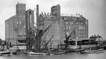 1. Engine No 12874 was installed in Marriage's new 'East Anglia Flour Mills' at Felixstowe Dock, Suffolk. Preparation of the site commenced in 1905 and the new mill was completed in 1907.
Right: Marriage's East Anglia Mills at Felixstowe Dock.
A history of the business (a) published in 1940 contains the following: "The engine house, together with its equipment, constitutes one of the most interesting features of the mill. The main engine - a Paxman Lenz tandem compound engine - was built and supplied by Messrs. Davey, Paxman & Co. Ltd., of Colchester. This engine, after thirty-three years of continuous service, has maintained its efficiency to a remarkable degree. The auxiliary plant consists of a Browett Lindley vertical compound engine, direct coupled to an electrical generator, and a Mather & Platt automatic fire pump."
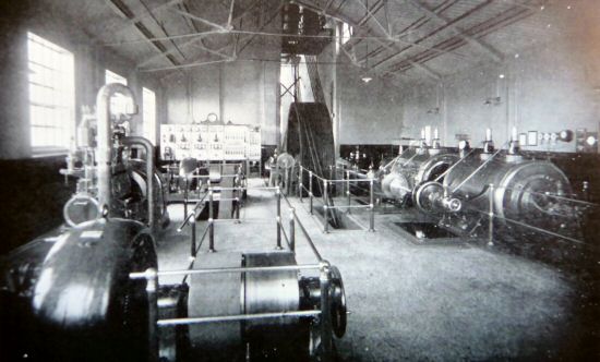
The Engine House at East Anglia Mills with the Paxman-Lentz to the right of the picture.
In 1940 a British bomber returning from France crashed into the mill which exploded in flames. A large part of the mill was demolished and it was out of action for two years. It may be that the disaster resulted in the Paxman-Lentz engine being damaged beyond repair. The mill closed in 2005 and was demolished in 2007.
a. The Annals of One Hundred Years of Flour Milling published by E Marriage & Son Ltd of Colchester and Felixstowe (there is no indication of authorship). Printed by Spottiswoode, Ballantyne & Co, Ltd. of Colchester, London and Eton. From the text it is clear the book was published in 1940.
Bibliography
1.Catalogue Illustré des Machines à Vapeur "Paxman," à Grandes Vitesses, À Distribution par Soupapes Accompagnées, Système "Lentz." Paxman-Lentz French catalogue - Publication No 204.
2. Paxman-Lentz Steam Engines, Davey, Paxman & Co Ltd catalogue - Publication No 723, dated May 1915.
3. Paxman-Lentz Steam Engines, Davey, Paxman & Co Ltd catalogue - Publication No 838. Undated but circa 1920/21.
Page updated: 11 Aug 2017