
Paxman and Steam Engineering
Quick links to topics on this page:
Introduction | Early Boilers | Portables | Horizontals | rue Saint-Fargeau, Paris | Standard Verticals
The Windsor | Peache Patent | High-Speed Triple Expansion Verticals | Paxman-Lentz
Steam Wagons | Traction Engines | Locomotives | 'River Esk' | Romney, Hythe & Dymchurch Rly
This page contains references to brake horsepower (BHP), indicated horsepower (IHP) and nominal horsepower (NHP).
BHP is a measure of the rate at which an engine does work measured by resistance to an applied brake (i.e. the power available from the engine to do useful work, discounting friction and energy losses within the engine itself). One horsepower = 550 foot lbs per second or 745.7 watt (in the USA 1 horsepower = 746 watt).
IHP is a measure of the total power produced by a piston engine. It is calculated from the Mean Effective Pressure on the piston during a power or working stroke, as derived from an indicator diagram, and the speed of the engine in revolutions per minute. Because of friction and energy losses within the engine itself, the power available from a stationary steam engine to drive another piece of machinery (i.e. its BHP) is generally reckoned to be around 90% of its IHP.
NHP, as used in steam engines ratings during the 19th and early 20th centuries, was a commercial unit used by engine manufacturers and purchasers. It was adopted by the Royal Agricultural Society in the 1840s to enable farmers to compare the power of a steam engine with that of a horse. NHP was calculated by reference to cylinder bore size and piston speed and, unlike BHP, was not a measure of an engine's actual power output. In the case of single cylinder steam traction engines, one NHP is broadly equivalent to between 6 and 7 BHP, but generally closer to 6 BHP. For a compound engine the figure may be closer to 7 BHP. On this basis a single cylinder 5 NHP traction engine might be expected to produce a little over 30 BHP. Stationary engines were much more conservatively rated. Information in early 20th century Paxman catalogues shows that for the Company's horizontal stationary engines one NHP was equivalent to only around 2 to 2½ BHP. The actual output of an engine depended not only on cylinder size but also on working steam pressure and engine speed. (For a fuller discussion see the page on Nominal Horsepower.)
Introduction
The early growth of the Company stemmed from its success with steam engines. This in turn derived from the ingenuity and abilities of James Paxman who was no newcomer to steam engineering when he started his business in 1865. For several years previously he had been Works Manager with the Colchester firm of Catchpool and Thompson where he was responsible for two unusual ventures. The first, in 1853, covered the design and construction of a steam carriage for a Captain Norrell, powered by a small engine with duplex cylinders. The vehicle was banned from the roads by the local authorities which brought its further development to an abrupt end. The second venture was much more successful. It consisted of designing and fitting twin steam engines in a tug boat to work river traffic for the Steam Navigation Commissioners between Sudbury and the lower Stour, just north of Colchester. At that time navigation of the river was difficult due to the many bends and shoals, and the production of a suitable shallow draft boat to fulfil such operating conditions was a great accomplishment. It commenced work on the River Stour in 1861 and operated very successfully for many years. When, therefore, James Paxman set up his own business he had already acquired considerable experience in the design and practical engineering aspects of steam engines.
Innovative Boilers
One of the business's first advertisements announced the partners were, inter alia, carrying on 'the Manufacture and Repair of Steam-engines & Boilers'. In the internal combustion age, interest in the steam engine itself can lead people to overlook the importance of the boiler. But then, as now, fuel economy was a key benchmark for potential engine purchasers and the efficiency of a steam engine's boiler was crucial. Much of James Paxman's early success with steam engines was due to his design and manufacture of very efficient and compact boilers. His personal interest and commitment in the quest for boiler efficiency was demonstrated by the fact that he himself undertook the stoking of the boiler during an engine trial in 1887. It is difficult to imagine many senior partners of successful firms in the 1880s being prepared to wield a stoker's shovel!
James Paxman was an innovator in the design and construction of boilers. In the early 1860s he came to the conclusion that the practice of ferruling boiler tubes was mistaken. Boilers without ferrules were first built in his Culver Street Works. He also pioneered the use of steel for locomotive type fireboxes, recognising it was less costly than the Lowmoor iron or the copper previously used and added materially to the life of the boiler. During the early years of the business experiments with the tubular boiler led to the evolution of the famous Paxman 'Economic' boiler which was the precursor of all other economic boilers.
Paxman was involved in boilermaking for over a hundred years. A detailed history of this major part of the Company's activities, and descriptions of most of the different types of boiler produced, can be found on the page Paxman Boilers - 1865 to 1969.
An Evolving Range of Engines
By 1870 the Company had produced its first steam engine which received a very favourable press. 'The Engineer' said of the boiler on which the engine was mounted, 'We have no hesitation in pronouncing it the best vertical boiler yet produced'. Of multi-tubular design with curved tubes, it was 2' 6" in diameter and 6' 6" high, with a heating surface of 73.9 square feet. The 6¼" bore x 12" stroke single cylinder vertical engine attached to it ran at 115 rpm. In trials at the 1870 Royal Agricultural Show the plant was the most economical tested, using only 6 lbs of coal per bhp hour.
The success of these stationary vertical engines and boilers encouraged the Company to start building portables and then horizontal stationary engines.
Portable Steam Engines
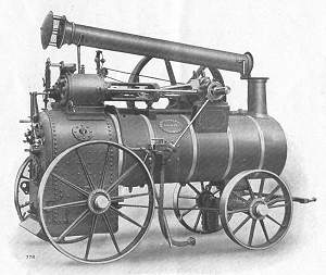 The first portable engine was exhibited at the Cardiff Show of the Royal Agricultural Society in 1872. The boiler was of the locomotive type but fitted with ten Paxman water tubes. These tubes were curved and connected the crown of the firebox with the sides, with the purpose of breaking up the gases on their way to the smoke tubes. The arrangement was successful, enabling the boiler to return the excellent figure of just over 10 lbs of water evaporated per pound of coal. The technical press commented, "This, Mr Paxman's first competitive portable engine, has proved in every respect so successful that we advise older firms to mind what they are about, or they may find themselves seriously beaten in the next competition".
Picture: A later portable shown in the Wearing Parts catalogue of 1913.
The next type of portable engine introduced further innovations. The single cylinder and its covers were all packeted and whole of the engine and motion was secured to a wrought iron frame of I-sections, these in turn being bolted to the boiler by suitable brackets. Simply by slackening a few bolts, the whole engine and motion could be removed from the boiler. At the Royal Agricultural Show at Newcastle-upon-Tyne in 1887 the Paxman engine returned the excellent figure of only 2.528 lbs of coal per bhp hour when running at its normal speed of 132 rpm. James Paxman personally stoked the engine, using his highly successful 'little and often' principle of firing. Steam pressure never varied by more than 1 psi during the run and the speed of the engine was almost perfectly uniform. After the four hours allotted running time for the trial the engine took over twenty minutes to run down during which time Mr Paxman burned the remaining ashes.
Two days later a Paxman compound engine with cylinders 5¾" x 9¼" with 14" stroke returned the even better figure of 1.804 lbs per bhp hour at 134 rpm using steam at 150 psi. As a result the Company carried off an award of £100 for the best single cylinder engine and a £200 prize for the best compound. The designing, building, and testing of one of the engines was accomplished in just eight weeks.
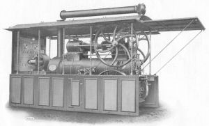 Special productions always had an appeal and one portable, generating electrical power for lighting, was designed for travelling showmen. The outfit was complete with DC generator mounted on a small front platform with the switchboard fixed to the end panel of the side curtain boards. The other end board was hinged and could be strutted up to form a shelter for the attendant. A side framing served as a fixing for the drop boards on each side, and from this framing the roof or canopy was supported on four square twisted brass columns, like those regularly adorning later showmen's engines. The whole plant was beautifully finished in the colourful style of contemporary travelling fairs.
Paxman made portables in large numbers, many of which were exported. For details and photographs of several which are still around see the Surviving Steam Portables page. During the Agricultural & General Engineers era (1920 to 1932) there was an agreement that the building of portables would be shared between Paxman and Richard Garrett & Sons of Leiston. Garrett was to make the single cylinder versions and Paxman the compounds. In accordance with this arrangement Garrett made sixty five Paxman 'badged' portables with Garrett engine numbers ranging between 33514 and 35245. Whether or not there was any subsequent formal variation to the agreement it is a fact that Paxman made several single cylinder portables after 1920.
Horizontal Stationary (or Fixed) Engines
Paxman's earliest horizontal stationary steam engines used motions based on those of the Company's portables. Relatively basic engines, they were made in small numbers, only eight being sold between April 1874 and April 1877. Later known as Class A engines, they were designed for a normal working steam pressure of 60 psi and had modest power outputs. At the 1879 Royal Agricultural Show Paxman launched a new range of horizontal girder engines, the Class B. This more powerful range of engines was designed initially for a working pressure of 120 psi and had a more sophisticated cut off valve arrangement. A more detailed description, outputs and dimensions can be found on the Class B page. Over time Paxman horizontal engines appeared in various forms such as condensing, non-condensing, coupled, compound and tandem compound.
A type of horizontal, sharing similarities to the portable from which it was derived, was the semi-fixed engine. Later known as the Undertype this had a locomotive type boiler with the motion located under the boiler barrel, rather than over it as in the case of the portable. The general arrangement made for a compact prime mover which proved attractive for electrical power generation installations in large private houses and institutions. Four of the earliest were 16 hp compounds built in 1882 for R E Crompton, the electrical contractor. Each had a 7½" bore HP cylinder, 13" bore LP cylinder, and a 12" stroke. One was for Octavius Coope of the brewing family for his Colchester home, Berechurch Hall, which was rebuilt about this time. The smaller sizes of this type of engine, 8 - 20 hp, were built initially on cast-iron bedplates, and were self-contained. The larger sizes, 25 hp and above, were built on a cast-iron girder frame, consisting of several parts bolted together, which facilitated transport and repairs. Paxman's Patent Automatic expansion gear was fitted to the high pressure cylinder, controlled by the governor, so that the cut-off was always proportional to the load. A catalogue description, picture, outputs and dimensions can be found on the Undertype Engine page.
During the 1880s the Company continued to expand its range of horizontal engines. A publication dated 1893 carried a full page Paxman advertisement which made reference to the following types:
| Horizontal Engines Class B | Single Cylinder 4 - 500 hp Double Cylinder 8 - 1,500 hp |
| Horizontal Engines Class A | Single Cylinder 4 - 50 hp Double Cylinder 8 - 150 hp |
| Improved Horizontal Coupled Girder Compound Engines | 8 - 1,500 hp |
| The "Colchester" Horizontal Fixed Compound Engine | 8 - 400 hp |
| Horizontal Condensing Engines Class C | 16 - 200 hp |
| New Patent Semi-Fixed Compound Engine and Boiler | 8 - 250 hp |
| Horizontal Winding Engines | |
| Tandem Compound Engines |
The "Colchester" Compound first appeared in 1883 and was manufactured in large numbers, many for export. Being self-contained on a girder frame, it required only a simple and cheaply made foundation. A description, picture, outputs and dimensions can be found on the Colchester Engine page.
Also introduced in the early 1880s was the Class C engine.
Tandem compound engines were arranged with the high and low pressure cylinders longitudinally in line with each other, both pistons being attached to a common piston rod, rather than the more familiar side by side arrangement for compound engines. An advantage of the arrangement was the requirement for only one connecting rod and a single crank crankshaft.
Coupled engines were those where one crankshaft connected two parallel horizontal engines. A common fly-wheel was mounted in the centre of the crankshaft between the cranks.
Winding engines were developed for winding and hauling in mining operations. They usually had a drum or drums mounted on the crankshaft, and between the cylinders when the engine was of the compound cross-coupled type. The Company's earliest winding engines were for diamond mines around Kimberley, South Africa, orders being received in 1878 and succeeding years.
From about 1910 the Class "K" horizontal engine replaced Paxman's older girder types. It was "specially designed to meet the demand for an inexpensive, yet reliable, steam engine capable of developing a large amount of power in proportion to the space occupied". A description, picture, outputs, dimensions and prices can be found on the Class "K" Engine page.
The most technically advanced and important of the Company's horizontal steam engines was the Paxman-Lentz, described later on this page. As a cheaper alternative to the Lentz, Paxman also offered its Drop Valve engine.
Surviving Paxman Stationary Steam Engines
Elsewhere on this website is a page with details and photographs of known surviving Paxman stationary engines, both horizontal and inverted vertical types: see Surviving Paxman Stationary Steam Engines
rue Saint-Fargeau, Paris
Among several large public and private installations of Paxman steam engines was a group of engines driving air compressors, together with the attendant battery of boilers, belonging to the Compagnie Parisienne de l'Air Comprimé (Paris Compressed Air Company).
In 1879 Victor Popp had founded his Compagnie des Horloges Pneumatique which ran large clocks (such as those in streets, railway stations and commercial premises) on compressed air. In 1881 he obtained from the municipal authorities in Paris a 50-year concession to build and operate a network of underground pipes in the city for distributing compressed air to these clocks. To supply the system Popp constructed a small air-compressing station at rue Saint-Fargeau, Belleville, about 4 miles from the centre of Paris. This opened in 1882 or 1883.
Popp subsequently recognised that his compressed air system had the potential to drive larger pieces of equipment than pneumatic clocks. In July 1886 he secured much wider powers from the Municipal Council of Paris to provide compressed air throughout the city for driving machinery of any kind. There were many small workshops in Paris that needed prime movers (engines) to drive equipment like printing presses, machine tools and sewing machines. Popp's system was well-suited to powering these prime movers, typically steam engines adapted to run on compressed air, and demand for compressed air grew rapidly. To meet the increasing demand it was decided to substantially enlarge the Saint-Fargeau station.
Paxman became largely responsible for designing the new plant for Saint-Fargeau and supplied for it six large coupled compound condensing girder engines, twelve compressors and nine boilers. These were ordered in January 1887. Each engine had a High-Pressure cylinder of 22" bore, a Low-Pressure cylinder of 35" bore, and a 48" stroke. Each had a 14 foot diameter flywheel and drove two compressors. The engines were probably Class C types. An 1883 Paxman catalogue described the company's newly-designed Class C horizontal engine as being mounted on a cast-iron girder frame and supplied with or without a condenser. The single-cylinder 50 NHP Class C offered in the 1883 publication had a cylinder bore of 22½", very close to the 22" bore of the High-Pressure cylinders of the Saint-Fargeau engines, and a 14' diameter flywheel as did the Saint-Fargeau engines. The latter, with their two cylinders, were rated 100 NHP, twice the power of the 1883 22½" bore single-cylinder Class C. The Paxman 'Economic' boilers were 14 foot long and 7' 6" in diameter. The enlarged Saint-Fargeau plant became operational in 1887 or 1888 and was claimed to be the largest compressed air system in the world.
Late in 1888 Popp's company secured the concession to light a large district in central Paris, two miles long and one mile wide, described as 'the most important section of Paris from an electric light point of view'. It was perhaps this district that received its power supply from the 'station centrale d'électricité' installed in the basement of the Bourse de Commerce (near Les Halles), in the first arrondissement, in about 1889. Here compressed air from the Saint-Fargeau plant was delivered through the underground pipe network to power four engines driving dynamos for electrical power generation. A text of the time speaks of three Paxman steam engines of 50 cv (chevaux) and one of 100 cv, driving 75 amp, 600 volt dynamos.
By 1889 Popp's Compagnie Parisienne de l'Air Comprimé had forty miles of pipes supplying 4,000 houses. The demand for compressed air had continued to grow until the Saint-Fargeau facility became unable to meet it during peak periods. It was decided, therefore, to further enlarge the plant to about double its size. In spring 1889 Paxman received repeat orders for engines and boilers but the Municipality of Paris insisted that a share of the new machinery should be constructed in France. This resulted in the repeat orders being cancelled, for which Paxman was compensated. Orders went instead to Société Cockerill of Seraing (Belgium) where, it was reported in July 1889, five new engines and compressors, with ten boilers to supply them, were in course of construction for Saint-Fargeau.
In addition to its engines installed at Saint-Fargeau, Paxman sold various other steam engines to Victor Popp and his company. Paxman also benefited from steam engine orders placed by larger industrial users of Popp's compressed air system. Details of Paxman orders received from Popp and his company, as recorded in the surviving Paxman copy Order Book of the period, are reproduced in Appendix A at the foot of this page.
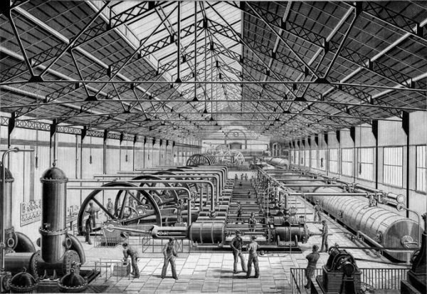
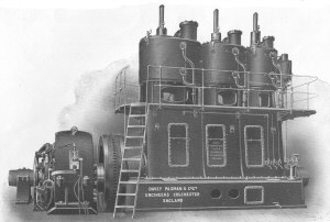
The rue Saint-Fargeau Engine House of the Compagnie Parisienne de l'Air Comprimé,
with its six Paxman coupled compound condensing girder engines.
Paxman's Standard Vertical Engines
 Some of the earliest steam engines made by Paxman were (inverted) vertical single cylinder types. They were relatively basic, reasonable priced, low power engines for which there was a ready market. Paxman sold large numbers of them and they made an important contribution to the early success of the business. This type of engine had a long life and was still appearing in Paxman catalogues of the mid-1920s. Although there were obviously changes to the design over the years, it is not difficult to see family likenesses between the ones sold in the 1870s and those pictured in a catalogue fifty years later.
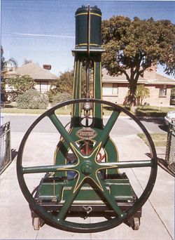
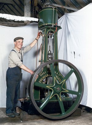
The oldest known surviving Paxman engine anywhere in the world is one of these single cylinder verticals. No 1402 was ordered on 25th January 1877 by Thomas Davey & Co of Melbourne, Australia. The 6½" bore x 12" stroke engine was rated at 4 NHP and has a 4½ foot diameter flywheel. It was acquired in September 2000 by the current owner, Mr Kym Zeitz who lives near Adelaide, South Australia. When purchased the engine was lying outside exposed to the elements, the cylinder head being occupied by a mud wasps' nest. Several key components were missing, such as the two slide valves, valve rods, the steam chest cover and throttling governor. Fortunately the cross head and bearings were in good condition. One of the major challenges facing Kym in his restoration was trying to find out details of the construction of the missing parts, particularly the unusual slide valves arrangement. Now completely restored, as pictured here, the engine runs smoothly on compressed air. An account of the restoration was published in the Aug-Sept 2003 issue of The Old Machinery Magazine (Australia). The intention is to complete restoration of a suitable boiler so that once again No 1402 can be run under steam.
Photo © Kym Zeitz and The Old Machinery Magazine 2003
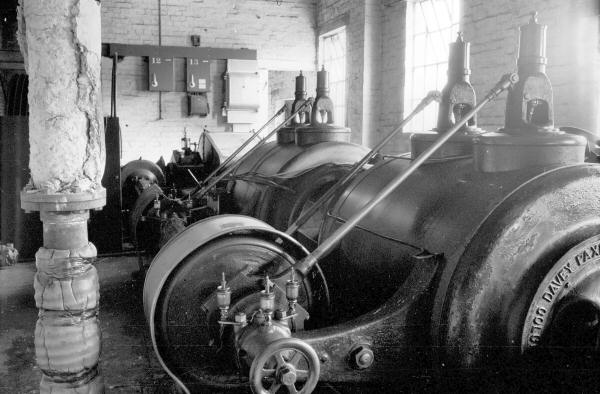
 Another well restored example of a similar type (pictured left) is to be found closer to Colchester, at West Mersea. The parentage of this engine is obvious from a comparison of the photograph above and the one to the left. Though there are many similarities in appearance to No 1402, the single slide valve arrangement of the later engine is much simpler. No 5483 was ordered on 17th March 1890 for the Mann Crossman & Paulin brewery in London and despatched from the Works on 15th August that year. Rated at 6 NHP, it has an 8½" bore x 12" stroke. Owned by Andrew Phillips of Colchester, the engine was restored in 1986 by the late Russell Weavers who also subsequently maintained it. Since its restoration the engine has been regularly steamed.
The direct descendants of these early verticals were Paxman's Class "SV" engines. Designed for customers requiring only a small power output, these single cylinder engines were made in six standard sizes from 2 NHP up to 10 NHP. Working at 80 to 100 psi, steam distribution was effected by a simple slide valve controlled by a variable expansion eccentric allowing the steam cut-off to be varied in proportion to the load. Provided with continuous lubrication to all working parts, the engine was designed to be capable of being left running for many hours without attention. A picture, outputs, and dimensions can be found on the Class "SV" Engine page.
The "Windsor" Engine
A later type of Paxman vertical was the "Windsor" which the Company developed in 1884/85. It was specially designed to meet the needs of electric lighting installations. This was during the very early days of electric lighting; scarcely five years after Joseph Swan and Thomas Edison had each patented their incandescent electric light bulbs. One requirement was that an engine should be capable of working for many hours without stopping. To this end the "Windsor" was provided with large wearing surfaces and special means of lubrication so that it could run for many months without adjustment. Paxman proudly claimed that "no expense is spared in the workmanship and finish of these engines" and the materials employed in the manufacture of parts "are of the very highest quality".
A second requirement was an engine and drive arrangement which could turn a dynamo at a steady constant speed. A frequent shortcoming in early electric light installations was the annoying and uncomfortable tendency of lamps to flicker because of variations in the speed of the dynamo and, consequently, the current generated. To overcome or minimise the potential problem, the "Windsor" was designed to be direct-coupled to a dynamo or alternator, unlike earlier Paxman engines which employed belt drive from the flywheel. Also the engine was fitted with a highly sensitive governor to closely control its speed with narrow limits.
The "Windsor" was produced in single cylinder, double cylinder, compound and triple-expansion forms. The single cylinder engines were relatively small and typically used for electric lighting plants in private houses of the wealthy. Compound versions were usually specified for larger installations. It is thought only a small number of triple-expansion types were built.
 One of the earliest "Windsors" was a 12 NHP compound installed in Windsor Castle in early 1886 as part of the Castle's first electric light plant. Queen Victoria subsequently granted James Paxman permission to use the "Windsor" name for his new range of engines.
Paxman exhibited a triple-expansion "Windsor" at the Crystal Palace Electrical Exhibition of 1892. The most powerful engine on show at the exhibition, it was designed to produce 350 IHP at 140 rpm, with a steam pressure of 160 psi, and was direct-coupled to a 145 kW Siemens multipolar dynamo.
Right: Engraving, taken from a photograph, of the 350 IHP "Windsor" shown at the 1892 Crystal Palace Electrical Exhibition.
Below are details of three major "Windsor" installations:
One of the largest installations of "Windsor" engines, if not the largest, must have been that of the Great Eastern Railway (GER) at Norton Folgate, just north of the GER's London Liverpool Street terminus. The GER decided in 1892 to build an electric lighting generating station, one of the earliest to be built by a railway company in Britain, to illuminate Liverpool Street Station and associated buildings. Colonel R E B Crompton, the leading British electrical engineer of his day, was appointed electrical contractor. He personally oversaw the electrical aspects of the installation and his company supplied the dynamos. The first orders for engines and boilers for the new power station were placed with Paxman in September 1892. These were for two 200 IHP "Windsor" compounds, 18" + 28½" bore x 18" stroke, three 100 IHP "Windsor" compounds, 12" + 18¾" bore x 15" stroke, and three 14' 6" long x 7' 6" diameter 'Economic' boilers. During the autumn of the following year, orders were placed for two more 200 IHP "Windsor" compounds when the GER decided to extend electric lighting to its Bishopsgate and Bethnal Green stations. The Norton Folgate power station was brought into use during November 1893. ( >> more on Paxman steam engines and boilers supplied to the GER.)
In October 1892 orders were placed by Julius Sax & Co, Electrical Engineers (who in 1900 were based at Eagle Works in Coldharbour Lane, Camberwell, London SE) for four 250 IHP "Windsor" compounds, of 18¾" + 30" bore x 18" stroke, and four Paxman Economic boilers. These were required for a lighting plant for London's Smithfield Meat Market and the engines were despatched from the Colchester factory in October 1894. Although the relevant order entry in the surviving Paxman copy order book seems to indicate that all four of the engines supplied for Smithfield were 250 IHP, it has been suggested that one of the four actually installed was the 350 IHP triple-expansion engine which originally provided power at the 1892 Crystal Palace Electrical Exhibition.
In July 1893 the Corporation of Cardiff placed an order for four Windsor engines and three Paxman Economic boilers. Two of the engines were 450 IHP (270 BHP) triple-expansion types with cylinder bores of 12¾" (13") (HP), 20" (Intermediate) and 31¼" (33") (LP) - the bracketed figures being those on the order. The stroke was 18" and the design speed 133 rpm. The other two engines were 100 IHP (65 BHP) compounds with cylinders of 10" + 16" bore x 12" stroke (the copy order book gives the HP cylinder as being of 8¾" bore), designed to run at 200 rpm. All four were sent to Canton, on the west side of Cardiff, in October 1893. 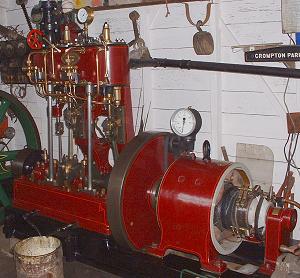 Here the engines were coupled to Siemens alternators. Initially certain technical characteristics of the AC generating system led to engine control problems when the two triple-expansion engines were running in parallel but, after a time, Paxman managed to find ways round the difficulties, as engineers usually do.
Pictured left is a surviving small 4 NHP "Windsor" compound, No 13035, of 4" + 6½" bore x 6" stroke, coupled to a Crompton dynamo. Built in 1906, it was originally supplied to Selby Urban District Council in Yorkshire. Like the single cylinder engine No 5483, mentioned in the previous section, this engine is now owned by Andrew Phillips of Colchester, and was restored and subsequently maintained by the late Russell Weavers. The engine has been steamed regularly since its restoration.
The only Paxman catalogue I have seen which contains details of the "Windsor" engine is No 207, Section C. (1) This offers 'The "Windsor" High-Speed Vertical Simple and Compound Steam Engines'. Powers and dimensions of standard sizes, as given on pages 70, 71 and 73, are as follows:
| "Windsor" High-Speed Vertical Simple Steam Engines. Single Cylinder Working pressure 90 psi. | ||||||||
|---|---|---|---|---|---|---|---|---|
| Nominal Horse- Power | Brake HP | Cylinder | Flywheel | |||||
| Economic Load | Maximum Load | Diameter | Stroke | Diam. | Width | Speed rpm | ||
| 4 | 8 | 12 | 6½" | 7" | 3' 6" | 5" | 290 | |
| 5 | 10 | 15 | 7¼" | 8" | 4' 0" | 5" | 260 | |
| 6 | 13 | 19 | 8¼" | 8" | 4' 0" | 6" | 260 | |
| 8 | 19 | 27 | 9½" | 9" | 4' 0" | 7" | 240 | |
| 10 | 24 | 34 | 10½" | 10" | 4' 6" | 8" | 217 | |
| 12 | 32 | 43 | 12" | 12" | 4' 6" | 8" | 180 | |
| "Windsor" High-Speed Vertical Simple Steam Engines. Double Cylinder Working pressure 90 psi. | ||||||||
| Nominal Horse- Power | Brake HP | Cylinder | Flywheel | |||||
| Economic Load | Maximum Load | Diameter | Stroke | Diam. | Width | Speed rpm | ||
| 8 | 16 | 24 | 6½" | 7" | 3' 6" | 7" | 290 | |
| 10 | 20 | 30 | 7¼" | 8" | 4' 0" | 8" | 260 | |
| 12 | 26 | 38 | 8¼" | 8" | 4' 0" | 9" | 260 | |
| 16 | 38 | 54 | 9½" | 9" | 4' 0" | 10" | 240 | |
| 20 | 48 | 68 | 10½" | 10" | 4' 6" | 11" | 217 | |
| 25 | 64 | 86 | 12" | 12" | 5' 0" | 12" | 180 | |
| "Windsor" High-Speed Vertical Compound Steam Engines Working pressure 140 psi. | ||||||||
| Nominal Horse- Power | Brake HP | Diam. of Cylinders | Stroke | Flywheel | ||||
| Economic Load | Maximum Load | High Press. | Low Press. | Diam. | Width | Speed rpm | ||
| 4 | 8 | 10 | 4" | 6½" | 6" | 3' 0" | 5" | 330 |
| 6 | 12 | 16 | 4¾" | 7½" | 7" | 3' 6" | 6" | 290 |
| 8 | 18 | 22 | 5½" | 9" | 7" | 3' 6" | 7" | 290 |
| 10 | 24 | 29 | 6½" | 10½" | 8" | 4' 0" | 8" | 260 |
| 12 | 29 | 34 | 7" | 11¼" | 8" | 4' 0" | 9" | 260 |
| 16 | 41 | 48 | 8" | 13" | 9" | 4' 0" | 10" | 240 |
| 20 | 50 | 60 | 9" | 14½" | 10" | 4' 6" | 11" | 217 |
| 25 | 62 | 75 | 10" | 16" | 12" | 5' 0" | 12" | 180 |
| 30 | 68 | 85 | 11" | 17" | 12" | 5' 0" | 14" | 180 |
| 35 | 90 | 105 | 12" | 18¾" | 15" | 6' 0" | 14" | 150 |
| 40 | 103 | 120 | 12¾" | 20" | 15" | 6' 0" | 16" | 150 |
Paxman "Peache Patent" High-Speed Single-Acting Engines
The Peache engine was developed to meet the needs of the changing electrical power generation market in the 1890s. Up to this time electric lighting was a luxury found mainly in large houses of the very wealthy and some public institutions. For several years Paxman had successfully supplied steam engines and boilers for this market, working with pioneering electrical engineers, contractors and generator manufacturers such as Col R E B Crompton and Edmundson. The 1890s saw the rapid growth of 'central electricity stations' supplying electricity for domestic lighting and business use, and plants generating power for electric traction, typically trams. Increasing numbers of local authorities started to commission the construction of electric light stations so that by 1903 all towns but two, with a population of more than 100,000, had an electricity supply. The prime movers favoured for driving dynamos in these power stations were multiple units of small high-speed steam engines, particularly the central valve type designed and built by Willans & Robinson of Thames Ditton.
Before 1895 Paxman did not have a high-speed engine which met the requirements of this increasingly important market. In early 1893 James Courthope Peache, who had previously worked for Willans & Robinson, wrote to James Paxman seeking to interest him in Peache's own design of a high-speed engine. After much consideration and negotiation it was agreed that Paxman would produce the Peache engine and J Courthope Peach was appointed Works Manager at Colchester.
 The 'Peache Patent' engine was launched at the 1895 Empire of India Exhibition at Earls Court where three of the new engines were put on show. The Peache was a unique type of inverted-vertical, high-speed, single-acting, tandem compound. Built and sold only by Paxman, around 260 were produced between 1895 and 1913 when the last was made.
High-speed engines became the preferred prime-mover for central electricity stations because they allowed the use of smaller and less costly dynamos than were required with low or medium speed engines. The more usual double-acting engines of the time tended to suffer from 'knocking' in the big-end bearings when run at high speed. To overcome the problem single-acting engines were adopted. With this type, backlash in the bearings could be avoided by maintaining the balance of pressure towards the crankshaft, even during the engine's return stroke. An unusual feature of the Peache's tandem compound arrangement was that the open ends of the high- and low-pressure cylinder castings were bolted to each other, with only the pistons separating the spaces inside each cylinder.
Most Peache engines were of a three-crank design, basically consisting of three vertical tandem compound engines connected to a three-crank shaft, the cranks being offset at 120° to each other. For smaller power outputs a single-crank design was offered and the surviving order records show that at least two 2-crank types were built.
The engine could not be described as a runaway success, either technically or commercially. It faced tough competition because, around the time of its launch, Belliss & Morcom introduced a highly successful double-acting engine. The latter featured forced lubrication of the crankshaft bearings, one of the earliest to do so, which largely overcame the knocking problems previously bedevilling high-speed double-acting types. Also, in the early years of the 20th century the steam turbine was establishing itself as a prime-mover in power generation. Turbines were a better solution for the higher power outputs required by the larger stations then being constructed to meet the growing demand for electricity.
One of the largest publicly-owned Peache installations was Colchester Borough Council's 'Electric Light Works' in Stanwell Street which became operational in late 1898. By 1905 it had seven Peache engines of varying sizes. A substantial private installation in north-east Essex was a power station constructed by the Great Eastern Railway for its port facilities at Parkeston Quay, near Harwich. This was equipped with three Peache engines and five Paxman 'Economic' boilers.
Fuller biographical details of James Courthope Peache, extensive technical information about his engine, and particulars of every Peache engine order received by Paxman can be found on the Peache Patent Steam Engines page.
High-Speed Triple Expansion and Compound Vertical Engines
 Paxman's 1905 Price List of its High-Speed Single-Acting Peache engines includes an advertisement for the Company's 'Double-Acting High-Speed Triple-Expansion and Compound Engines'. (2) Designed primarily for electrical power generation, these were not built in large numbers.
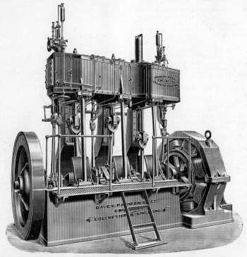
Right: Illustration from a photograph of a 750kW Double-Acting High-Speed Triple Expansion Engine, as supplied to Paisley Corporation Electricity Works.
The Peache price list gives the following details of double-acting high-speed triple-expansion engines Paxman had supplied (order book details have been added in italics):
| Customer | Number of Engines | Output |
|---|---|---|
| Ealing Corporation Electricity Works (Order No 7274 of 7 Mar 1904, 20" + 28" + 40" bores (stroke not specified).) | 1 | 825 kW. |
| Paisley Corporation Electricity Works (One a Repeat Order) (Order No 7203 of 27 Nov 1903, 20" + 29" + 41" x 18", sent 9 Jul 1904, and Order No 7530 of 19 Dec 1904, 20" + 29" + 41" x 18". Paisley Corporation had previously been supplied with an Mcc Peache engine under Order No 6663 of 27 May 1902.) | 2 | 750 kW. |
| Barking Urban District Council Electricity Works (Order No 7594 of 8 Mar 1905, 15" + 20½" + 30½" bores (stroke not specified), sent 2 Nov 1905. Coupled to Johnson & Phillips dynamo.) | 1 | 500 kW. |
| Swindon Corporation Electricity Works (Order No 7545 of 5 Jan 1905 ?) | 1 | 375 kW. |
| Admiralty, for Sheerness Dockyard (Order No 7484 of 19 Oct 1904, 13" + 19" + 24" x 11", placed by The Lancashire Dynamo Co.) | 3 | 300 kW. |
| Admiralty, for Sheerness Dockyard (Order No 7483 of 19 Oct 1904, 9" + 17½" x 8" (i.e. compound, not triple-expansion), placed by The Lancashire Dynamo Co. ) | 1 | 100 kW. |
| Koffyfontein Mines Limited | 1 | 250 kW. |
| SUBSEQUENT ORDERS FOR TRIPLE-EXPANSION ENGINES (i.e. not shown in Peache engine price list.) | ||
| Derbyshire & Nottinghamshire Electric Power Company, Ilkeston (Order No 7615 of 21 Sep 1906, 3 Triple Expansion DA Engines 1,250 IHP?, 20" + 29" + 41" x 18", sent 27 Apr 1906. The order date here, as entered in the copy order book, is after the delivery date, and appears among orders entered in March 1905.) | 3 | |
| Engineering Company of Australia for Townsville, Queensland. (Order No 7867 of 27 Jan 1906, 300 IHP Triple Expansion Vert Engine, 11½" + 20" + 32" bores (stroke not specified), sent on 28 Aug 1906.) | 1 | 300 IHP. |
| Colchester Corporation (Order No 7914 of 9 Mar 1906, Triple Expansion Vert Engine, 16½" + 25" + 40" bores (stroke not specified).) | 1 | |
| Paisley Corporation (Order No 7988 of 28 May 1906, One Triple Expansion DA Engine, 20¾" + 29¾" + 42" bores (stroke not specified), sent 12 Dec 1906. See above for previous Paisley Corporation orders.) | 1 | |
| Bo'ness, Scotland (Order No 8869 of 23 July 1908, One TJ Triple DA High-Speed Engine, 11¼" + 18½" + 30½" bores (stroke not specified). Engine No. 14862, sent 1 Oct 1908. Order placed by National Electric Construction Co which in January 1904 had ordered two Paxman 'Peache Patent' engines for Bo'ness: Paxman Order No 7245.) | 1 | |
| Rhondda Valley, South Wales (Order No 9069 of 25 March 1909, Triple Expansion DA High-Speed Engine, 12½" + 18½" + 30½" bores (stroke not specified). Engine No. 15084, sent 22 June 1909. Order placed by National Electric Construction Co.) | 1 | |
Paxman-Lentz Stationary Steam Engines
The Lentz engine, developed by Dr Hugo Lenz (1859-1944), made its first appearance at the Como Exhibition of 1899 where it won first prize. At the Paris Exhibition the following year it was awarded the Grand Prix and its inventor the Gold Medal. The engine became highly successful, principally because of its very economical steam consumption. Another important attribute was its capability of running for long periods at high piston and crankshaft speeds. Lentz engines were built by various manufacturers in mainland Europe, notable MAN in Germany, and by Erie City Iron Works in the USA.
Paxman obtained exclusive rights in Britain to use Lentz patents and started building Paxman-Lentz engines at Colchester in 1907. The Company's 1915 brochure about this type of engine cites among its special advantages: high speed, silent running, extreme economy in steam consumption, and simplicity of design. (3) Embodying Lentz patents covering positive valve gear, the governor, and frictionless metallic packing, the Paxman-Lentz proved so economical and reliable it virtually displaced every other type of large stationary steam engine produced by Paxman.
Horizontal tandem compound Paxman-Lentz, No 22351, at the sawmill of J W Ward & Son Ltd,
Bourne End, near Hemel Hempstead, Herts on 18th June 1980. Engine removed in 1982 and scrapped c.1990.
Photograph courtesy of and © Chris Allen.
The most important features of the design were the poppet valves and valve gear which controlled high-pressure superheated steam far better than other valve arrangements in use at the time. Not only was the Lentz much more economical than its competitors, it ran quietly and could operate at higher speeds with minimal wear on components, resulting in a much reduced need for maintenance.
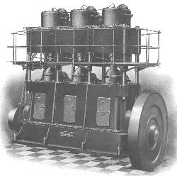
About 130 Paxman-Lentz engines were built at Colchester between 1907 and 1934. All but two were horizontal types. With the exception of twelve single cylinder engines, all were compounds; mainly tandem compounds. Many were used for driving generators or alternators where the effectiveness of the patent Lentz governor in closely controlling engine speed under conditions of varying load was particularly advantageous.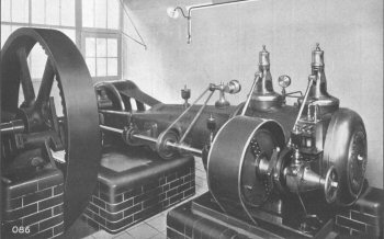 Several were supplied for driving refrigeration compressors which were also built by Paxman. Others were used for driving machinery in mills and factories in a wide range of different industries. Apart from a laboratory test engine for University College, London, one of the smallest built by Paxman was a single cylinder, 10" bore x 21" stroke, 60 bhp engine for the Maidenhead District Laundry Co. The largest, and one of the last to be made at Colchester, was a 1,200 IHP horizontal tandem compound, with 25" and 37½" bores and a 33½" stroke, for Wallpaper Manufacturers Ltd at Darwen in Lancashire, delivered in February 1932.
One of two single cylinder Paxman-Lentz engines supplied to The Maidenhead District Laundry Co Ltd.
Only two Paxman-Lentz engines are known to have survived. As at 2010, one is stored in a dismantled state in Somerset. A history, description and photographs of this engine can be found on the page Paxman-Lentz Steam Engine - No 18581. The other survivor, No 18842, currently stands in a disused wood mill in Bangkok. A picture and information about this engine is on the page Surviving Paxman Stationary Steam Engines.
Full technical descriptions of the features of Paxman-Lentz engines are given on the page Paxman-Lentz Steam Engines. Also on that page are a transcript of the May 1915 Paxman-Lentz brochure with tables of dimensions and power outputs, a detailed listing of all orders for Paxman-Lentz engines, including information on customers and applications, and a detailed listing of over 30 Lentz conversions carried out by Paxman on other makers' engines.
During the 1920s Paxman also became involved in making Lentz valves and valve gear for steam locomotives. The history of this activity can be found on the page Lentz Valves for Locomotives.
Bretherton Steam Wagons
 In May 1905 the Company received from Bretherton & Bryan of Willesden, London NW, an order for 'Three sets of Steam Motor Wagons'. These five-ton steam wagons, legalised by the passing of the Heavy Motor Car Order, were designed by Frank Bretherton who, at the time, was in partnership with a Mr L C Bryan. The latter had served his apprenticeship with Paxman, which may well explain why the Colchester company was approached to build the vehicles.
A Bretherton wagon at Paxman's works, before being fitted with bodywork.Photo © Paxman Archive Trust.
One of the distinctive features of the design was the top-fired short locomotive type boiler. The fire was fed through the firebox crown, the chute taking the place of crown stays. Built for a working pressure of 180-200 psi, the boiler supplied steam to a horizontal compound reversing engine mounted underneath the wagon's platform. The engine had cylinders of 5" and 7¾" bore x 9" stroke, with the steam chests below, and drove the rear axle through a geared arrangement to give road speeds of 2½ or 5 mph. The first wagon was sold to H H Finch of Marylebone, a wine merchant, and was fitted with a box body. Another was exhibited at the Agricultural Hall Motor Show, Islington, in March 1906. In his book Steam and The Road to Glory, Andrew Phillips notes that "much to (James) Paxman's irritation, Bretherton proved unable to pay for" the wagons. Perhaps part of the explanation is that by late 1906 Bretherton had withdrawn from the partnership with Bryan and the business had become Messrs Bryan and Company. Bretherton was an engineer and designer of note who at some stage in his career worked for Paxman and knew William Fletcher (see below). After the First World War he worked for Messrs Robey & Co Ltd of Lincoln, designing their well-known overtype compound steam wagon and other products. (4)
Paxman Traction Engines
Paxman built steam traction engines from 1906 up to 1917. They were designed by William Fletcher who, fortuitously for both parties, offered his services to the Company at the very time Paxman was considering moving into this field and looking for a suitably qualified engineer for the task. William Fletcher joined the Company in 1906 and came with impeccable credentials. Born in 1848, he was apprenticed to Marshalls of Gainsborough in 1863. Seven years later he moved to Wallis & Steevens of Basingstoke where he designed their first traction engine. 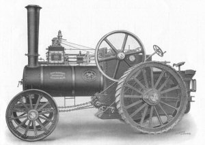 From 1878 he worked for Charles Burrell at Thetford for two years before returning to Marshalls to become their chief draughtsman. His subsequent appointments were as traction engine designer: first with Ransomes Sims & Jefferies from 1888, then with Clayton & Shuttleworth of Lincoln from 1897, and finally with Davey Paxman. He died at Cromer in Norfolk, probably in late 1918 but certainly no later than January 1919. (5)
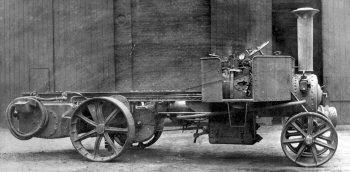
Illustration of Paxman Traction Engine from a 1913 catalogue
Old order books show the Company received 91 orders for traction engines. A number of these were cancelled with some of the relevant engines being allocated to later orders. The vast majority of Paxman traction engines were sold to customers in England. Several were made initially for major agricultural shows where they were exhibited and offered for sale. Export orders included two for Latvia, two for Barcelona, one for Italy, two (cancelled) for South America, and a 'Darby Digger' for Alexandria, Egypt. A full listing of Paxman traction engine orders can be downloaded from the Download page.
The engines were available in six single cylinder sizes. The smallest was a 4 NHP Steam Tractor weighing under five tons, designed to meet the requirements of the Local Government Board's Motor Regulations. The other five were General Purpose Traction Engines, rated from 5 to 10 NHP. Also offered was a 7 NHP compound road locomotive. By far the most popular was the 7 NHP single cylinder. The bore and stroke of each type, and numbers ordered, are shown in the table below.
| Horsepower | Bore | Stroke | Number Ordered |
|---|---|---|---|
| 4 NHP | 6" | 9" | 1 |
| 5 NHP | 8" | 10" | |
| ? NHP Darby Digger | 5" & 8" | 9" | 1 |
| 6 NHP | 8" | 12" | 20 |
| 7 NHP | 8½" | 12" | 54 |
| 7 NHP Compound | 6" & 9" | 12" | 2 |
| 8 NHP | 9" | 12" | 11 |
| 10 NHP | 10" | 12" | 2 |
An unusual piece of agricultural machinery derived from the traction engine was the Darby Digger, sometimes known as the 'Colchester' digger. Designed and made at the Standard Ironworks under the direction of a Thomas Churchman Darby, it consisted of a traction engine fitted with two sets of digging forks operated by built-up levers. The levers received their motion directly from the engine crankshaft, one being 90 degrees out of phase with the other. The order books only refer to one of these being made by Paxman.
More detailed technical specifications, descriptions of surviving Paxman traction engines and of scale models appear on the page Paxman Steam Traction Engines.
Steam Railway Locomotives
This page covers only Paxman steam locomotives. For the history of Paxman-engined diesel locomotives see the page Paxman and Diesel Rail Traction.
A locomotive supplied in 1869 to Brownlee & Co, Havelock, New Zealand for a logging railway is reputed to have been built by Paxman. In a book by the late Roland Abbott there is a photograph of this very crude four wheel engine, with a vertical boiler, hauling a truck carrying a large log. Another source suggests Paxman only supplied the boiler. Surviving Paxman order records do not go back far enough for any details to be checked.
Paxman records do show orders, Nos 2032 and 2033, placed in December 1881, each for a "4-wheel Loco Engine 18" Gauge". They were despatched to Port Elizabeth in June and July 1882 for operation in the Kimberley diamond mines. James Paxman, a great self-publicist, makes no reference to these engines, either in contemporary publicity material, anecdotes in speeches, or a paper he read to the Institution of Civil Engineers in 1883 about his exploits in Kimberley. This makes Andrew Phillips think the whole project was a disaster. Unfortunately we have no pictures of the engines.
'River Esk' - Ravenglass and Eskdale Railway (RER)
The next steam railway locomotive built by Paxman, despatched from the works on 12th December 1923, was for the Ravenglass and Eskdale Railway in Cumbria. Originally opened in 1875, the RER had a 3' gauge until its closure in 1913. At that time W J Bassett-Lowke, of model railway fame, and a group of fellow enthusiasts were looking for somewhere to lay an extensive 15" narrow gauge railway. The RER was well suited to their requirements so it was purchased and re-opened in 1915 after conversion to 15" gauge.
With the opening of granite quarries at Beckfoot in 1923, it was decided the railway needed a new locomotive for the anticipated mineral traffic. The engine would need to be capable of hauling 32 ton goods trains on grades of up to 1:34 and operating the heavy non-stop holiday passenger traffic in summer.
In 1922 the consulting engineer to the railway, Henry Greenly the leading model engineer of his day, drew up plans for a one-third scale model of a projected 2-8-2 main line goods locomotive. Deciding who should build the engine posed a problem. Bassett-Lowke had ceased making 15" gauge locomotives in 1914 and had no intention of resuming. A shareholder in the RER was Sir Aubrey Brocklebank, Chairman of the Cunard Steamship Company. Cunard was a large customer of Paxman and Sir Aubrey asked Paxman if they were interested in building a 'one off' miniature locomotive. The Company agreed and the order, No 15074 (Works No 21104), was placed on 21st March 1923.
'River Esk' was the first 2-8-2 locomotive to run on a British railway. Greenly's original designed was modified to incorporate Paxman-Lentz poppet valves and the Paxman patent valve gear then being introduced by the Company for locomotive use. Although Lentz valves had been fitted to locomotives on the continent some years previously, 'River Esk' was the first British locomotive to be fitted with them. The Lentz valves arrangement was not a success and in 1928 was replaced by more conventional Walschaerts gear.
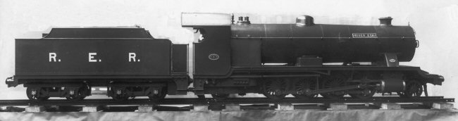
River Esk at Paxman's Standard Works before despatch to Ravenglass.
Having two cylinders of 5¼" bore x 8½" stroke, the engine was capable of a tractive effort of 2,100 lbs and pulling a load of 70 tons on the level. The overall length of engine and tender was 23' 3". Initially it was estimated the locomotive would weigh 6 tons 5 cwts. but a large bogie tender was fitted which brought the weight of the engine in working order to a little over 8 tons inclusive of the tender with 176 gallons of water and 5 cwts of coal.
The Romney Hythe & Dymchurch Railway (RHDR)
The story of subsequent orders for 15" gauge locomotives revolves around two very wealthy men, Capt J E P Howey (d.1963) and Count Louis Zborowski. Both famous racing drivers in the early 1920s - Zborowski raced the original Chitty Bang Bang - they shared a passion for narrow gauge railways. Each was sufficiently wealthy to be able to afford a 15" gauge railway on his estate. At one stage they tried to purchase the Ravenglass and Eskdale Railway but were unsuccessful.
Howey and Zborowski asked Henry Greenly to design a 15" gauge locomotive for them. They wanted the fastest, most impressive 15" locomotives ever built and planned to use them initially on Zborowski's private estate, Higham Park at Bridge, near Canterbury. Greenly drew up plans for a one third scale model based on Nigel Gresley's famous A1 4-6-2 Pacifics of the LNER, of which 'The Flying Scotsman' is a well known example. After approving the design, Zborowski ordered two of these locomotives from Paxman in 1924. Sadly, before they were completed Zborowski was killed whilst competing in the Italian Grand Prix at Monza in October 1924. Howey decided to take over the order and create a mainline in miniature as a memorial to his friend.
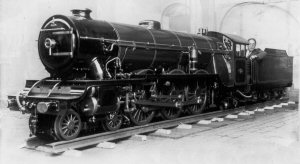 The two locomotives were completed at Standard Works in 1925 at a cost of £1,250 each. As Howey had no suitable track of his own, the first locomotive, DP (Davey Paxman) 15469, was despatched to the Ravenglass & Eskdale Railway in June 1925 for a month of trials. After acquitting herself well in the trials the engine was returned to Colchester for minor rectification work and named 'Green Goddess'. Pictured here is the locomotive whilst at Paxman's Works with Henry Greenly in the cab. The second locomotive, DP 15470, was named 'Northern Chief'.
Photo: Green Goddess with Henry Greenly in the cab at Paxman's Works in 1925.
The search for somewhere to build a railway took Howey and Greenly to Romney Marsh on the Kent coast where they found a suitable site. Greenly was told to proceed with the land purchase for what was to become the Romney Hythe & Dymchurch Railway. 'Green Goddess' and 'Northern Chief' were dispatched from Colchester and stored in the corner of a garage at New Romney until track could be laid. The engines were in use by 1926, with the line being formally opened on 16th July 1927.
Early in 1926 the Ministry of Transport indicated its willingness to grant the application for an Order under the Light Railways Acts so Howey ordered another locomotive that year to the same design as 'Green Goddess' and 'Northern Chief'. 'Southern Maid' (DP 16040) was delivered to the RHDR on 20th April 1927. The order was later expanded to include a further four locomotives. Two of these were Mountain Class 4-8-2 goods locomotives, 'Hercules' (DP 16041) and 'Samson' (DP 16042), to handle heavy shingle/ballast traffic anticipated from the County Council's tips near Hythe. Completed in 1927 at Colchester, they were similar in most details to the first three Pacifics apart from their smaller driving wheels and different wheel layout.
The final two, the last steam locomotives to be made by Paxman, were also built in 1927. 'Typhoon' (DP 16043) and 'Hurricane' (DP 16044) were Pacifics similar to the first three, except they were originally designed and fitted with a third cylinder placed between the frames. In practice the addition of the third cylinder provided no useful enhancement of performance, increased fuel consumption, and was dogged by frequent breakdowns. Consequently 'Typhoon' was converted to two cylinder operation by Paxman in 1935 and 'Hurricane' by the RHDR's own workshops in 1937.
All seven Paxman locomotives for the RHDR were designed to operate at a steam pressure of 180 psi and, with the exception of 'Typhoon' and 'Hurricane', had two cylinders. Cylinder sizes, including those of the three cylinder variants, were the same as 'River Esk', 5¼" bore x 8½" stroke. In full working order, inclusive of water and fuel, the weight of the Pacifics was approximately 8 tons. The overall length of engine and tender of the Pacifics was 24' 5", and of the Mountains 25'.
A further two English type two-cylinder locomotives, similar to the first three, were ordered from Paxman in September 1927. After the Company had allocated order numbers 16692 and 16693 the order was cancelled. In 1929 RHDR decided to adapt the design to American type Pacifics and put in hand the building of two locomotives in their own workshops. The boiler work was contracted out to Krauss of Munich, and some other parts were procured from Paxman. Ultimately all the parts that were to hand were sent up to Sheffield where the building of the locomotives was completed in 1931 by the Yorkshire Engine Co who were full scale locomotive builders. The first engine was originally named 'Dr Syn' and the second 'Black Prince'. When the first was renamed 'Winston Churchill' in 1948, the 'Dr Syn' plate was transferred to 'Black Prince'.
Order details for all the above locomotives, as recorded in a surviving Paxman copy Order Book, are reproduced in Appendix B below. More about the locomotives and RHD Railway, together with colour photographs, can be found on the Romney Hythe & Dymchurch Railway website which is well worth a visit as, of course, is the railway itself.
Lentz Valves for Locomotives
The section above about 'River Esk' mentions that the 15" gauge locomotive was originally fitted with Paxman-Lentz poppet valves. During the latter half of the 1920s Paxman supplied Lentz valves for a number of mainline locomotives both in the UK and overseas. Sir Nigel Gresley tried them on various locomotives of the LNER. The venture was not the success Paxman had hoped for. A detailed account of the Company's activities in this field can be found on the page Lentz Valves for Locomotives.
Changing Technology and New Directions
By the late 1920s Paxman was successfully manufacturing heavy oil engines which, for their customers, had many advantages over steam. From then on the future of Paxman lay with the development of the large high-speed diesel for which it is now best known. The last Lentz-Paxman engine, built for a laundry, was delivered in 1934, marking the end of steam engine manufacture at Standard Works. However boiler manufacturing remained an important part of the business. Paxman continued to make large shell boilers until 1967 and did not finally cease its boilermaking activities until 1969. Thereafter the Company continued to utilise the specialist knowledge and skills developed through boilermaking, such as plating and welding, in the design and manufacture of large rotary vacuum filters for a wide variety of applications. The Process Plant Division as it came to be known was sold to Brackett, another Colchester filtration business, and transferred to their site at the end of April 1989, freeing Paxman to concentrate on its diesel engine activities.
Bibliography and References:
Steam and the Road to Glory, Andrew Phillips, Hervey Benham Charitable Trust 2002, ISBN 0 9529360 1 1
1. Illustrated Catalogue of Vertical Steam Engines, Winding & Hauling Machinery and Air Compressors, Davey, Paxman & Co Ltd Publication No 207, Section C (undated but perhaps c.1906/7 ?).
2. Price List of High-Speed Single-Acting Engines (Peache Patent), Davey, Paxman & Co Ltd price list - Publication No 57, dated July 1905.
3. Paxman-Lentz Steam Engines, Paxman catalogue - Publication No 723, dated May 1915.
4. Road Locomotive Society Journal, Vol. 2, Issue 1, August 1948, p. 1.
Road Locomotive Society Journal, Vol. 5, Issue 3, December 1951, pp. 4-5. Obituary - F J Bretherton.
The Engineer, March 30, 1906, p. 320.
Commercial Motor, May 4, 1905. p. 162, and March 29, 1906.
5. Ransomes Sims & Jefferies, Agricultural Engineers, A History of Their Products, Brian Bell, Old Pond Publishing, 2001, ISBN 1 903366 15 1. Reference to William Fletcher on p 85.
The Engineer 127 (1919). Willliam Fletcher's death reported on p 10.
Appendix A
Orders Received from Victor Popp and his Compagnie Parisienne de l'Air Comprimé
| Order No | Date | Description | Cylinder | Who for / Where sent | Date sent |
|---|---|---|---|---|---|
| 2693 | 24-02-1886 | 1 NHP Vertical Engine | 3½" x 6" | Who for: V Popp Where sent: Paris | 30-10-1887 |
| 2694 | 24-02-1886 | 2 NHP Vertical Engine | 4½" x 9" | 30-10-1887 | |
| 2697 | 05-03-1886 | 4 NHP Class A Engine | 6½" x 12" | 12-04-1886 | |
| 2698 | 05-03-1886 | 4 NHP Class A Engine | 6½" x 12" | 12-04-1886 | |
| 2699 | 05-03-1886 | 6 NHP Class A Engine | 8¼" x 12" | 12-04-1886 | |
| 2747 | 22-06-1886 | 6 NHP Class A Engine | Who for: Victor Popp Where sent: Paris | 03-08-1886 | |
| 2748 | 24-06-1886 | 10 NHP Class A Engine | 17-08-1886 | ||
| 2773 | 26-08-1886 | 6 NHP Class A Engine | 13-09-1886 | ||
| 2786 | 29-09-1886 | 6 NHP Class A Engine | 06-11-1886 | ||
| 2793 | 22-10-1886 | 4 NHP Class A Engine | 12-02-1887 | ||
| 2802 | 06-11-1886 | 6 NHP Class A Horizontal Engine | 06-11-1886 | ||
| 2810 | 04-01-1887 | Four Compound Engines | |||
| 2811 | 04-01-1887 | Eight Compressors | |||
| 2812 | 04-01-1887 | Six Boilers | |||
| 2813 | 04-01-1887 | Four Condensers | |||
| 2815 | 03-12-1886 | 6 NHP Class A Horizontal Engine | 27-01-1887 | ||
| 2827 | 31-12-1886 | 14 NHP Class B Girder Engine | 12¾" x 20" | 24-07-1886 | |
| 2832 | 20-01-1887 | 6 NHP Class A Horizontal Engine | 12-02-1887 | ||
| 2833 | 24-01-1887 | Two 100 HP Compound Girder Engines | |||
| 2834 | 24-01-1887 | Three 7' 6" x 14' Economic Boilers | |||
| 2835 | 24-01-1887 | Four Air Compressors | |||
| 2836 | 24-01-1887 | Two Condensers | |||
| 2837 | 24-01-1887 | Piping for Connections | |||
| In the surviving copy order book for this period there are no entries after 16-03-1887 until 18-07-1888. It is particularly unfortunate as this was an important period for the expansion of Victor Popp's venture in Paris. | |||||
| 3142 | 16-08-1888 | Two Double Cylinder Class A Engine | 12" x 14" | Who for: Compagnie Parisienne de l'Air Comprimé Where sent: Paris | 20-10-1888 |
| 3156 | 31-08-1888 | Four 14' 6" x 7' 6" Economic Boilers | 8/14 Kilos | 19-01-1889 | |
| 3183 | 11-10-1888 | Six 3 NHP Standard Vertical Engines | 5½" x 9" | Dec 1888 - Jan 1889 | |
| 3184 | 11-10-1888 | Three 4 NHP Vertical Engines | 6½" x 12" | ||
| 3185 | 11-10-1888 | Six 25 NHP Class A Engines | 12" x 14" | ||
| 3186 | 11-10-1888 | Coupled Horizontal Compound Girder Engine | 22" + 35" x 48" | ||
| 3189 | 18-10-1888 | 6 NHP Class A Engine | 8¼" x 12" | 20-11-1888 | |
| 3209 | 14-11-1888 | Four 6 NHP Class A Engines | 8¼" x 12" | Dec 1888 - Jan 1889 | |
| 3248 | 30-01-1889 | 8 NHP Class A Engine | 9½" x 12" | ||
| 3270 | 04-03-1889 | Six 25 NHP Double Cylinder Class A Engines | 12" x 14" | 17-06-1889 | |
| 3320 | 20-06-1889 | 20 NHP Locomotive Type Boiler | WP 75 psi | 01-07-1889 | |
| 3321 | 20-06-1889 | 25 NHP Locomotive Type Boiler | WP 75 psi | 17-09-1889 | |
| 3322 | 20-06-1889 | Two 25 NHP Locomotive Type Boiler | WP 75 psi | 12-08-1889 | |
| There is no record of Paxman having received any more orders from the Compagnie Parisienne de l'Air Comprimé after 20-06-1889. | |||||
Appendix B
Orders Received for 15" Gauge Railway Locomotives
The following details have been extracted from surviving Paxman copy order book Number 6.
River Esk - Ravenglass & Eskdale Railway
Order No: 15074
Date: 21st March 1923
Description: 8 Wheeled Coupled Mineral Locomotive
Regd No: 21104
Who for: Ravenglass & Eskdale Railway
Where sent: Ravenglass
Date sent: 12th December 1923
Green Goddess (DP 15469) - Romney Hythe & Dymchurch Railway
Order No: 15469
Date: (blank, but immediately following entry for Order No 15468 of 12th July 1924)
Description: 15" Gauge Railway Locomotive
Regd No: 21499
Who for: Count Zborowski
Where sent: Ravenglass Romney, Kent
Date sent: 20th June 1925 16th November 1925
Northern Chief (DP 15470) - Romney Hythe & Dymchurch Railway
Order No: 15470
Date: (blank, but immediately before entry for Order No 15471 of 16th July 1924)
Description: 15" Gauge Railway Locomotive
Regd No: 21500
Who for: Count Zborowski
Where sent: Romney, Kent
Date sent: 16th November 1925
Southern Maid (DP 16040) - Romney Hythe & Dymchurch Railway
Order No: 16040
Date: (blank, but immediately following entry for Order No 16039 of 12th November 1925)
Description: Railway Locomotive
Arrangement: 4-6-2
Regd No: 22070
Who for: New Romney & Dymchurch Railway
Where sent: Kent
Date sent: 20th April 1927
There is a photographic image of this locomotive at Colchester with 'Southern Chief' name plates before the name was changed to 'Southern Maid'.
Hercules (DP 16041) - Romney Hythe & Dymchurch Railway
Order No: 16041
Date: (blank)
Description: Railway Locomotive
Arrangement: 4-8-2
Regd No: 22071
Who for: New Romney & Dymchurch Railway
Where sent: Kent
Date sent: 20th April 1927
There is a photographic image of this locomotive at Colchester with 'Man of Kent' name plates before the name was changed to 'Hercules'.
Samson (DP 16042) - Romney Hythe & Dymchurch Railway
Order No: 16042
Date: (blank)
Description: Railway Locomotive
Arrangement: 4-8-2
Regd No: 22072
Who for: New Romney & Dymchurch Railway
Where sent: Kent
Date sent: 20th July 1927
Typhoon (DP 16043) - Romney Hythe & Dymchurch Railway
Order No: 16043
Date: (blank)
Description: Railway Locomotive
Arrangement: 4-6-2
Regd No: 22073
Who for: Captain Howey
Where sent: King's Cross Station
Date sent: 19th May 1927
There is evidence that Typhoon was despatched to King's Cross before 1st May as there is a photograph of it, alongside Flying Scotsman (4472) at King's Cross, which is dated 1st May 1927. The two locomotives were brought together at King's Cross for publicity photographs. Typhoon was subsequently delivered to New Romney on 19th May, the 'sent' date entered in the order book.
Hurricane (DP 16044) - Romney Hythe & Dymchurch Railway
Order No: 16044
Date: (blank, but immediately before entry for Order No 16045 of 17th November 1925)
Description: Railway Locomotive
Arrangement: 4-6-2
Regd No: 22074
Who for: Captain Howey
Where sent: (blank, but presumably Kent)
Date sent: 20th July 1927
Romney Hythe & Dymchurch Railway
Order No: 16692
Date: 9th September 1927
Description: Two Cylinder Pacific Locomotive
Regd No: 22722
Who for: Romney & Dymchurch Railway
Where sent: Hythe, Kent
Date sent: (blank - order cancelled)
Romney Hythe & Dymchurch Railway
Order No: 16693
Date: 9th September 1927
Description: Two Cylinder Pacific Locomotive
Regd No: 22723
Who for: Romney & Dymchurch Railway
Where sent: Hythe, Kent
Date sent: (blank - order cancelled)
Preparatory work had been done for the last two locomotives before the orders were cancelled. The parts that had already been made were delivered to New Romney where they remained for some time. Eventually they were sent to the Yorkshire Engine Company at Sheffield where two locomotives were completed for the RHDR in 1931.
Acknowledgements: Among those who assisted with information for this page and answered many queries were the late Michael Johnson, formerly Paxman's librarian and archivist, the late Mike Gipson, formerly of MAN B&W Diesel Ltd, Paxman, and the late Alex Walford. I am also grateful to R Kenway for providing information on Frank Bretherton and his wagons.
Page updated: 17 Jul 2017 at 20:16