
NacoPax Road Making Plant
Paxman's venture into the manufacture of asphalt mixing plant was relatively short-lived. The order for the prototype was placed in March 1923. Virtually all the plants, and associated items such as steam portables to drive them, had been delivered by mid-1926. On another page of this site you can find the text of Paxman's Catalogue No 905 which describes its NacoPax plant.
Road Asphalt Mixing Plant
The years following the First World War saw increasing use of asphalt as a binder in road surfacing materials. This bitumen based substance has a much higher melting point than coal tar which had generally been used for the purpose up to that time. A demand therefore arose for mixing plant which could both operate at the higher temperature required to melt asphalt and adequately dry aggregate before the two were mixed. As it was not practical at that time to transport hot asphalt for more than ten miles or so, a further requirement was that mixing plant should be capable of being moved to a new site as and when required to keep deliveries within an acceptable radius.
Neuchatel Asphalte Co Ltd and Paxman
During the early 1920s the Neuchatel Asphalte Co Ltd (NACo) started to develop its road surfacing business in Britain. In the latter part of 1922 Neuchatel's requirement for a number of asphalt mixing plants came to the attention of Major Stewart, Davey Paxman's London representative. Paxman urgently needed the work which had the added attraction of complementary orders for its portable steam engines to drive the plants. The Company was willing therefore to invest the necessary effort in designing and developing what was initially called Nacopax Road Making Plant, subsequently Nacopax Road Makers. The order for the prototype was placed on 6th March 1923 and delivered in October that year.
Paxman was no stranger to the road asphalt business before its involvement with Neuchatel. In January 1922 it received orders for two 12 NHP compound portables (Nos 20793-4) from New Bradshaws' Asphalte Co which were despatched to Deptford. Between February 1922 and February 1923 it received orders for seven portables from the Whitehall Asphalte Co: four 10 NHP compounds, one 14 NHP and one 20 NHP double cylinder engine, and a single cylinder 12 NHP. These were despatched to Trafford Park, Romford, Holme, London (2), Huntingdon and Earlestown. One wonders whether Bradshaws' was bought by Whitehall and if Whitehall was subsequently acquired by Neuchatel. There is no overlap between the dates when each of these companies placed orders with Paxman.
A detailed description of the Nacopax plant appeared in 'The Engineer' of Nov 13, 1925, on pages 528-530. The text of that article and two of the line drawings which accompanied it are reproduced lower down this page.
To design, build and deliver a completely new plant of this type in little over seven months from date of order was no mean achievement. Unfortunately the compressed timescale did not permit extended field trials which might have revealed some of the plant's shortcomings and provided an opportunity to remedy them during development. One related to capacity. The 80 tons per day output was more than one gang of men could lay in a shift but insufficient to keep two gangs busy. A second weakness arose from the 'double pass' design of the drum which was actually two drums, one rotating inside the other. Although this made for a more compact machine than the main competitor (an American design), the arrangement for supporting the inner drum tended to interfere with the smooth flow of aggregate through the outer drum. A third problem area was the bearings. A decision was made to use sealed ball bearings throughout which seems eminently sensible in view of the constant exposure to dust and grit. Unfortunately the high operating temperature of the plant melted and expanded the grease, forcing it out of the bearings. The loss of lubrication and ingress of grit led to short bearing life. Despite these faults, one authority says the plants had a useful life and a total of 18 were built.
The Neuchatel Asphalte Company, which during the mid-1920s had its London head office in Victoria Street, eventually became part of what is now the Tarmac Group.
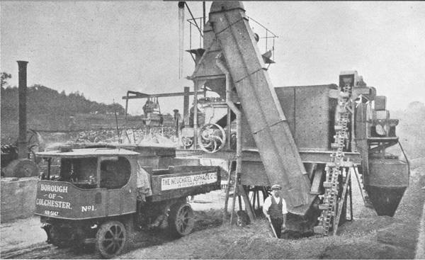
Pictured above is a Nacopax asphalt mixing plant at work in early 1926 at the Hythe, Colchester, just a few minutes walk from Paxman's Standard Works on Hythe Hill. On the far left is the Paxman portable steam engine driving the plant. Further local interest is provided by the Borough of Colchester's No 1 steam wagon, a Sentinel, in the foreground. The drop side on the back of the wagon carries the Neuchatel company's livery.
Nacopax Orders
Paxman order book entries, reproduced in the table below, show that twenty one Nacopax Road Makers were ordered between 1923 and 1925. All were for the Neuchatel Asphalte Co with the exception of the final order which was placed in the name of George Wimpey & Co. It is possible that not all were delivered. For three plants the 'Sent to' and 'Date Sent' columns are blank so these could have been cancelled or allowed to lapse. It is interesting to note Nacopax machines were dispatched to Australia, Tasmania, New Zealand, Italy and Germany as well as to depots in England and Scotland.
| Date of Order | Number | Sent to | Date Sent |
|---|---|---|---|
| 6th March 1923 | 21095 | Fulham | 11th October 1923 |
| 20th December 1923 | 21323 | Hythe, Colchester | 24th May 1924 |
| 18th February 1924 | 21367 | Epping | 10th July 1924 |
| 18th February 1924 | 21368 | Barkingside | 23rd August 1924 |
| 18th February 1924 | 21369 | Dumbarton | 10th June 1925 |
| 18th February 1924 | 21370 | ||
| 11th June 1924 | 21473 | Australia | 13th September 1924 |
| 11th June 1924 | 21474 | New Zealand | 10th February 1925 |
| 11th June 1924 | 21475 | Hobart | 23rd April 1925 |
| 11th June 1924 | 21476 | Berlin | 6th May 1925 |
| December 1924 | 21634 | Billericay | 16th June 1925 |
| December 1924 | 21635 | Pinner | 22nd June 1925 |
| December 1924 | 21636 | Epsom | 2nd July 1925 |
| December 1924 | 21637 | Italy | 21st July 1925 |
| December 1924 | 21638 | Durham | 11th August 1925 |
| 6th May 1925 | 21783 | Stroud | 8th September 1925 |
| 6th May 1925 | 21784 | Rutherglen | 19th February 1926 |
| 6th May 1925 | 21785 | Melbourne | 18th November 1925 |
| 6th May 1925 | 21786 | ||
| 23rd May 1925 | 21820 | Geo Wimpey & Co, Folkestone | 29 Mar 1926 |
Ancillary Equipment
The Nacopax work brought with it orders from Neuchatel for a good deal of ancillary equipment. Looking at the 'Sent to' and 'Date Sent' columns in the tables above and below, many of the items listed below were clearly supplied for use with particular Nacopax machines listed above. Excluding orders for steam portables, which are listed in the next section, the Neuchatel orders for additional equipment were as follows:
| Order Number | Date of Order | Description | Number | Sent to | Date Sent |
|---|---|---|---|---|---|
| 15103 | 19 Apr 1923 | Six Bitumen Boilers | 21133 | Fulham | 2 - Oct 1923 1 - Nov 1923 3 - Jul 1924 |
| 15367 | 11 Mar 1924 | One set of Trestle Gear | 21397 | Colchester | 26 May 1924 |
| 15412 | 05 May 1924 | Three sets Trestle Gear | 21442 | Hythe, Colchester | 08 Jul 1924 (blank) 10 Jun 1925 |
| 15413 | 05 May 1924 | One set of Lifting Gear | 21443 | Dumbarton | 26 May 1924 |
| 15447 | 11 Jun 1924 | Four sets Trestle Gear | 21477 | Australia New Zealand Hobart Berlin | 13 Sep 1924 10 Feb 1925 23 Apr 1925 06 May 1925 |
| 15492 | 11 Aug 1924 | One set of Lifting Gear | 21522 | Australia | 13 Sep 1924 |
| 15504 | 03 Sep 1924 | Two Groups Rotary Powder Roasters | 21534 | Fulham | 1 set 27 Feb 1925 |
| 15531 | Oct 1924 | Bitumen Handling Gear | 21561 | Barkingside | 27 Nov 1924 |
| 15602 | 17 Dec 1924 | Air Lift for boilers | 21632 | Fulham | 16 Mar 1925 |
| 15609 | 19 Dec 1924 | 5 sets Trestle Gear | 21639 | Billericay Pinner Epsom Italy Durham | 16 Jun 1925 22 Jun 1925 02 Jul 1925 21 Jul 1925 11 Aug 1925 |
| 15634 | 28 Jan 1925 | One set of Lifting Gear | 21664 | Auckland | 12 Feb 1925 |
| 15658 | 16 Feb 1925 | Rotary Powder Roasters | 21688 | Fulham | 06 Jan 1926 |
| 15726 | 15 Apr 1925 | Two sets of Lifting Gear | 21756 | (blank) | 07 May 1925 21 May 1925 |
| 15727 | 15 Apr 1925 | One Air Lift for Nacopax | 21757 | Pinner | 14 Aug 1925 |
| 15738 | 24 Apr 1925 | Cold Bitumen Handling Gear | 21768 | Hobart | 18 Jun 1925 |
| 15745 | 01 May 1925 | Bitumen Hoist & Winch | 21775 | Berlin | 25 Mar 1926 |
| 15746 | 01 May 1925 | Bitumen Hoist & Winch | 21776 | Stroud | 26 Mar 1926 |
| 15749 | 01 May 1925 | Two sets of Lifting Gear | 21779 | Billericay Italy | 17 Jun 1925 01 Jul 1925 |
| 15757 | 06 May 1925 | Trestle Gear Four Sets | 21787 | Rutherglen Stroud Melbourne Italy | 19 Feb 1926 08 Sep 1925 18 Nov 1925 21 Jul 1925 |
| 15758 | 08 May 1925 | Bitumen Hoist | 21788 | Melbourne | 18 Nov 1925 |
| 15786 | 22 May 1925 | Four Bitumen Hoists | 21816 | Pinner Melbourne Rutherglen | (blank) 17 Nov 1925 23 Feb 1926 |
| 15791 | 23 May 1925 | 1 Set Trestle Gear | 21821 | Geo Wimpey & Co, Folkestone | (blank) |
| 15847 | 09 Jul 1925 | Air Lift | 21877 | Italy | (blank) |
| 15852 | 14 Jul 1925 | One set of Lifting Gear | 21882 | on loan Wimpey | 29 Mar 1926 |
| 15853 | 14 Jul 1925 | One Bitumen Hoist | 21883 | Billericay | 19 Mar 1926 |
| 15969 | 10 Oct 1925 | Air Lift | 21999 | Berlin | 25 Mar 1926 |
| 15975 | 16 Oct 1925 | Air Lift for Nacopax | 22005 | Melbourne | 21 Nov 1925 |
| 16022 | 06 Nov 1925 | Air Lift | 22052 | Hobart | 18 Jan 1926 |
| 16023 | 06 Nov 1925 | Air Lift | 22053 | Rutherglen | 23 Feb 1926 |
| 16024 | 06 Nov 1925 | Air Lift | 22054 | Durham | 12 Mar 1926 |
| 16025 | 06 Nov 1925 | Air Lift | 22055 | Billericay | 19 Mar 1926 |
| 16026 | 06 Nov 1925 | Air Lift | 22056 | Stroud | 26 Mar 1926 |
| 16027 | 06 Nov 1925 | Air Lift | 22057 | Hythe | |
| 16028 | 06 Nov 1925 | Air Lift | 22058 | Naples | 25 May 1926 |
| 16029 | 06 Nov 1925 | Air Lift | 22059 | Cardross | 04 Jun 1926 |
| 16030 | 06 Nov 1925 | Air Lift | 22060 | Fulham | 14 Jul 1926 |
| 16031 | 06 Nov 1925 | Air Lift | 22061 | ||
| 16032 | 06 Nov 1925 | Air Lift | 22062 | ||
| 16157 | 30 Mar 1926 | Bitumen Hoist & Runway | 22187 | ||
| 16158 | 30 Mar 1926 | Bitumen Hoist & Runway | 22188 | ||
| 16159 | 30 Mar 1926 | Bitumen Hoist & Runway | 22189 | ||
| 16160 | 30 Mar 1926 | Bitumen Hoist & Runway | 22190 |
Among the above orders are some for lifting gear, trestle gear and air lifts. Lifting gear was required to raise Nacopax plant to the required height when it was being erected on a new site. (Sufficient headroom was necessary to enable wagons to reverse under the plant for loading.) Once the plant was in place it was supported on cheaper trestle gear (steel A frames) and the lifting gear removed for use elsewhere. Air lifts were pieces of ancillary equipment for lifting melted bitumen up to the mixer on top of the plant. Air lifts relied on the use of a small Westinghouse air compressor mounted on the side of the portable steam engine used for driving the main plant. Compressed air was fed to a steam jacketed cylinder containing the melted bitumen which was forced under pressure up to a measuring skip over the mixing machine.
Portable Steam Engine Orders
As previously mentioned, one of the initial attractions to Paxman of the Nacopax business was the prospect of additional orders for its portable steam engines. In this they were surely not disappointed. Neuchatel ordered a total of 29 portables although it is possible that not all were actually taken. (Two were built for Paxman by Garrett of Leiston, perhaps under AGE arrangements for sharing portables work between the two companies.) More than half the orders were for large 12 HP compound engines. From 1923 to 1925 Neuchatel was by far the largest British customer for Paxman portables, and virtually the last. Paxman sold scarcely a handful of portables after 1925. The Neuchatel orders were as follows:
| Order Number | Date of Order | Description | Number | Sent to | Date Sent |
|---|---|---|---|---|---|
| 15222 | 19 Sep 1923 | 12 HP Compound Portable Engine 7" x 11¼" x 14" | 21252 | Hythe (Colchester?) | 14 Feb 1924 |
| 15223 | 19 Sep 1923 | as above | 21253 | as above | 22 Apr 1924 |
| 15433 | 22 May 1924 | L12 Portable Engine (Garrett WS III - 12NHP Single Cyl.) | 34580 | Folkestone | 09 Jul 1924 |
| 15434 | 22 May 1924 | as above | 34581 | Epping | 14 Jul 1924 |
| 15479 | 30 Jul 1924 | 12 HP Compound Portable. wp 140 psi | 21509 | Billericay | 17 Jun 1925 |
| 15480 | 30 Jul 1924 | 12 HP Compound Portable. wp 140 psi | 21510 | Pinner | |
| 15481 | 30 Jul 1924 | 12 HP Compound Portable. wp 140 psi | 21511 | Epsom | 02 Jul 1925 |
| 15482 | 30 Jul 1924 | 12 HP Compound Portable. wp 140 psi | 21512 | Stroud | 07 Sep 1925 |
| 15483 | 30 Jul 1924 | 12 HP Compound Portable. wp 140 psi | 21513 | Sydney | 16 Oct 1924 |
| 15528 | 26 Sep 1924 | 3½ HP Portable Engine | 21558 | Barkingside | 17 Dec 1924 |
| 15663 | 19 Feb 1925 | 3 HP S.C. Portable Engine | 21693 † | 11 Mar 1925 | |
| 15747 | 01 May 1925 | 3 HP Portable Engine | 21777 | Pinner | 27 Aug 1925 |
| 15748 | 01 May 1925 | 3 HP Portable Engine | 21778 | Melbourne | 21 Nov 1925 |
| 15769 | 18 May 1925 | 3½ HP S.C. Portable Engine | 21799 | Rutherglen | 19 Feb 1926 |
| 15770 | 18 May 1925 | 3½ HP S.C. Portable Engine | 21800 | Bridgeton | 19 Feb 1926 |
| 15771 | 18 May 1925 | 3½ HP S.C. Portable Engine | 21801 | Hythe Colchester | 20 Apr 1926 |
| 15772 | 18 May 1925 | 12 HP Compound Portable Engine OB | 21802 | Stroud | 19 Feb 1926 |
| 15773 | 18 May 1925 | 12 HP Compound Portable Engine OB | 21803 | Rutherglen | 12 Mar 1926 |
| 15774 | 18 May 1925 | 12 HP Compound Portable Engine OB | 21804 | Hythe Colchester | 21 Apr 1926 |
| 15775 | 18 May 1925 | 12 HP Compound Portable Engine OB | 21805 | Carluke | 23 Mar 1926 |
| 15803 | 10 Jun 1925 | 12 HP Compound Portable Engine | 21833 | ||
| 15804 | 10 Jun 1925 | 12 HP Compound Portable Engine | 21834 | ||
| 15805 | 10 Jun 1925 | 12 HP Compound Portable Engine | 21835 | ||
| 15807 | 10 Jun 1925 | 3 HP S.C. Portable Engine | 21837 | Fulham | 28 Mar 1927 |
| 15808 | 10 Jun 1925 | 3 HP S.C. Portable Engine | 21838 | ||
| 15809 | 10 Jun 1925 | 3 HP S.C. Portable Engine | 21839 | ||
| 15810 | 10 Jun 1925 | 3 HP S.C. Portable Engine | 21840 | ||
| 15811 | 10 Jun 1925 | 3 HP S.C. Portable Engine | 21841 | Billericay | 21 May 1926 |
| 15984 | 19 Oct 1925 | 12 HP Compound Portable Engine | 22014 | Australia | 20 Nov 1925 |
† No 21693, is now in preservation. It ended its working life near Billericay in Essex and may have been delivered there when new although the order book is silent on this point. Nos 21509 and 21841 were dispatched to Billericay which suggests Neuchatel had a depot or large contract in the area.
Text of article published in The Engineer Nov 13, 1925, pages 528-530.
An Asphalt Mixing Plant.
It is rather remarkable, in view of the extensive road-making programmes which have been carried out in this country within the past year or so; and also considering the fact that our roads are now acclaimed as the best constructed in the world, that British road contractors have been largely dependent on foreign-made plant in carrying out their work. The situation has, however, been appreciated by several of our manufacturing engineers, and there are now available plants for the preparation of road-making materials of purely British construction.
The plant which we illustrate by the half-tone engravings on page 529 and the line drawings herewith, made by Davey, Paxman and Co., of Colchester, is what is commonly known as an asphalt drying and mixing plant, but the name is not really quite precise, as it is not generally asphalt that is dealt with, but a mixture of bitumen and convenient aggregate. There have, of course, been several types of plant for this purpose in service in this country for some time past, but they have been principally of American origin. The Paxman plant is, however, essentially British in design and manufacture, while it has the merit of being what is often described as an "engineering job," as distinct from some machines made abroad that are rather flimsy in their construction.
The two essential functions which have to be performed by an "asphalt" plant are the drying of the aggregate, to drive off any moisture which it may have accumulated in storage in the open, and the incorporation of the aggregate with the bitumen necessary to bind it together and make a waterproof material. The relative proportions of the several ingredients naturally vary with the requirements. Thus the lower layers of a road surface contain a larger proportion of stone, while the "carpet" or wearing surface is little more than sand and bitumen. Intermediary there is the "binder," which comprises a mixture of stone, sand, bitumen and a "filler," which is generally Portland cement.
The rate at which stone can be dried is naturally greater than that for sand, but it is, nevertheless, generally found most convenient to dry them together in approximately the proportions required for the road surface. The ingredients are then exactly proportioned, mixed together and laid while still hot from the drying operation.
Although some successful experiments have been made on the laying of bituminous macadam cold, it is generally considered preferable to lay it hot, and as a consequence the radius which can be served by a mixing plant is dependent on the distance to which the material can be transported before it becomes too cold. The distance is generally put at about 10 miles, and when it has been exceeded the plant must, obviously, be moved to a new site. It is thus necessary that the mixer should be reasonably portable; but, in view of the rough conditions of road-contracting work, the machinery must, at the same time, be of a robust nature. It appears to us that Davey, Paxman and Co. have been very successful in combining these two characteristics, as the plant weighs in running order approximately 14 tons, and it can be set to work within a day of arriving on the site. The process of erection will be described later; and it will, perhaps, be best first to describe the essential parts of the plant.
The dryer is the most important item, and in the Paxman plant it takes the form of a double concentric drum, about 4ft. 6in. in diameter by 11ft. long. One of these drums is shown very plainly in the half-tone engraving - Fig. 1 - while its construction is illustrated in the line drawing - Fig. 2. The two drums are made of boiler plate, about ½in. thick, and are braced together by straps - as shown in Fig. 1 - with a clear annular space between the two shells.
Unlike some plant, in which the drying drum is set on an incline, the drum in the case under review is set horizontally - an arrangement which has the advantage that end thrust is eliminated. In order to feed the stone along, the dryer is fitted, inside, with a series of small castings. These castings are riveted onto longitudinal bars, which can be readily bolted in place, and are of such a form that they "cascade" the material over in the drum and, at the same time, plough it forward to the outlet. This action is so thorough that some of the stone in the annular space is actually carried right over the top of the inner drum and falls on the opposite side, which, naturally, greatly increases the drying capacity as compared with a drum in which the material merely rolls about in the bottom. The drying is also facilitated by the contraflow system of feeding. That is to say, the stone is fed into the inner drum, through the shoot D - Fig. 2 - and after working its way to the other end of this drum falls into the annular space and returns to the outlet. At the same time the hot furnace gases go into the drum, where the stone emerges, and are discharged at the inlet. The drum is mounted on rollers at each end, and these rollers have double-row Skefco ball bearings. The whole of the bearings about the machine, with one small exception, are, in fact, of this type and a large amount of power is consequently saved in driving the machine.
It has been mentioned that the horizontal arrangement of the drying cylinder obviates end thrust on its bearings but it is, of course, necessary to fix the axial position of the drum in its casing, and for that purpose there are two ball-bearing rollers on opposite side of the carrying flange at the inlet end. The housings of these rollers, together with those which carry the weight of the drum are mounted on slides, and can be adjusted into position by means of screws. The power for rotating the drum is provided by gearing keyed to one of the carrying rollers at one end, and it is noteworthy that although the dryer weighs nearly 3 tons, it can be revolved, through the gearing, comfortably by hand.
With the exception of the extreme ends, the drying drum is enclosed by a steel casing lined with fire-brick, and, below, there is the furnace, which is, of course, also brick-lined. These linings are built up, just clear of the steel casing, so as to provide an intervening air space, and are held in place by clips riveted on to the casing. We felt some anxiety as to the ability of the brickwork to withstand the rough usage meted out to most contractor's plant, and consequently made some inquiries in that direction. One user of these plants assured us that he had experienced no troubles through loose brickwork; while we were shown a casing that had been accidentally dropped from a crane, through a sling slipping, and there was not a brick out of place.
Working in conjunction with the dryer there are two "cold" elevators, one on either side of the plant, which are used to raise the sand and aggregate up to the inlet level. These elevators are of the simple chain-and-bucket type, as can be seen in several of the half-tone engravings, and have smooth driving wheels, instead of sprockets, while the idlers run on ball bearings. The smooth driving wheels provide ample grip for normal service, and also act as a slipping, safety device in the event of the elevator being overloaded. Another elevator - see Fig. 2 - is used to take the dried aggregate from the delivery end of the drum up to the storage bins above the mixer. All three of these elevators are of the same pattern, but the two "cold" sets have the alternate buckets omitted, as their combined output has, of course, to be taken away by the one "hot" elevator. The capacity of the several elevators is in excess of the demands of the mixer when running at full output, and the actual rate of delivery of the materials is regulated by the men feeding them to the two cold elevators. It will be noticed that the elevator for the hot materials is boxed in, to conserve heat as far as is possible.
The draft necessary for keeping the fire going and for drawing the products of combustion through the drying drum is provided by means of a fan connected with the outlet end of the central drum, as shown at K in Fig. 2. This fan is, by the way, the only instance throughout the plant in which plain journals instead of ball bearings are adopted, and these bearings are provided with a simple form of water cooling. The gases discharged by the fan are led into a cyclone dust extractor, which can be plainly seen in some of the engravings, to prevent any fine dust, that may be carried by the aggregate, from being blown about the plant. The dust is collected on the ground below the cyclone, and is, we believe, sometimes used as a "filler" in the final mixing, although Portland cement is generally preferred for the purpose.
The dried aggregate is raised by means of the hot elevator - marked M in Fig. 2 - to the top of the plant, and is delivered into a rotary screen P running transversely across the machine. This screen separates the stone from the sand and delivers the two, individually, to separate hoppers. There is also a fixed screen over the stone hopper to prevent the access of any large lumps of material which might damage the mixer.
Directly below the hoppers, marked Q in Fig. 2, there is a weighing bin S, which is balanced by means of a steelyard, and the outlets from the hoppers to the bin are controlled by hand-operated doors R. The steelyard is of a peculiar form, and is provided with a series of stops, so that the balance weight can be set quickly, and without much consideration, as to the weight of the ingredients.
The weighing bin is commanded by the outlets from both aggregate hoppers, and it is consequently a simple matter to weigh out the necessary quantities of the stone and sand, and then to discharge them into the mixer T below. The melted bitumen is brought up to the same place by means described later, the filler is added by hand - its amount does not justify mechanical handling - and the whole batch is mixed together by the rotary arms of the mixer. The mixer does not require any description, as its construction is so obvious in the drawing, but it is noteworthy that it is responsible for the greater part of the power consumption of the whole plant. Thus the process of mixing requires some 10 horse-power, while the whole plant can be run with 17 horse-power.
The business of melting the bitumen, ready for addition to the aggregate is common to all types of this class of plant, and one of our illustrations shows a set of three bitumen "boilers" in service in Australia, in conjunction with a Paxman mixing plant. The method of conveying the melted bitumen to the mixer is, however, open to several alternatives. In some cases it is hoisted up, by block and tackle, in buckets; in others it is pumped, but what appears to be the most satisfactory arrangement is an "air lift."
The general arrangement of such an air lift is represented in Fig. 10, which shows a small Westinghouse air compressor mounted on the side of the portable engine used for driving the plant in general. On the ground, near to the bitumen boilers, there is a steam-jacketed cylinder of such a capacity that it will hold ample bitumen for a batch of mixture. This container is connected with the boilers by means of 3in. piping and cocks, which are all steam jacketed. The method of jacketing the cocks can be readily followed in Fig. 11, and the steam necessary for heating purposes is provided by the exhaust from the air compressor. A simple system of interconnected cocks is used to connect the container with the bitumen boiler and to atmosphere, and with the pressure air, so that the bitumen which has gravitated into the container may be forced up to a measuring skip over the mixing machine. The tall stand pipe shown in Fig. 10 is, of course, provided to allow the air in the container to be exhausted to atmosphere, in preparation for the next cycle of operations, without any loss of bitumen. It is noteworthy in connection with these Paxman air lifts that all the parts are substantially made, well jacketed and easy of access for cleaning. In Fig. 10 the apparatus is shown with connections for two bitumen boilers.
We have already referred to the importance of making plant of this nature reasonably portable, and Messrs. Paxman have devised a process by means of which it can be got to work as expeditiously as possible.
One of the first considerations is that the plant must be at such a height that the mixed material will gravitate into a lorry run beneath the mixer, which means that the main framing must be 7ft., or so, above ground level. It is obvious that such a bulky plant could not be conveyed to the site of operations at such a height, and it is consequently necessary to raise it when it arrives.
The dryer and mixer, with the furnace and elevators, &c., removed, make a convenient load for a lorry, and the unit is brought to the site in that form, with the smaller parts loaded up separately. A set of four tripods is then erected round the machine for lifting it off the lorry. These tripods are well illustrated in Figs. 7 and 8, from which it will be seen that they comprise tubular legs with a worm gear at the top for operating the nut of a long square-threaded screw. The lower end of the screw is attached to the framing of the plant, and a man at each of the lifting gears can easily raise the whole machine. When the requisite height has been attained, the lorry is drawn out and another wagon carrying the furnace is run under the main framing. A set of long bolts is used to pull the furnace up into place, and the smaller parts are put in position with the assistance of a little jib crane mounted over the mixer.
The lifting tripods are obviously too valuable to be used as permanent supports for the plant, as they can be used for another lifting job elsewhere, while they are not entirely rigid. For this reason a set of simple A frames is slipped in place when the plant is up to the proper height and the weight is transferred to them, so that the lifting tackle may be released.
The capacity of these plants is about 10 tons an hour when mixing "carpet" material, or 15 tons an hour for binder, and they will give an average output over the whole day of 12 tons an hour when mixing ¾in. road metal. The power required is about 17 horse-power, and the total fuel consumption for drying the aggregate, for melting the bitumen and for driving the machinery is, we are informed, from 0.5 cwt. to 0.6 cwt. of coke per ton of mixture when the raw aggregate contains from 6 to 7 per cent. of moisture. This fuel consumption includes that necessary for keeping the bitumen boilers hot during the night, when the mixer is out of commission.
See also:
In addition to the above article, pictures of the plant at work were published in the following week's issue of 'The Engineer' (Nov 20, 1925), opposite p 632, accompanied by a description of the plant on pp 631-632.
Paxman publication No 904 'Instructions for Erection and Working of NacoPax Asphalt Drying & Mixing Plant', c.1925/6.
Paxman publication No 905 'NacoPax Asphalt Road Plants - Asphalt Drying & Mixing Plant', c.1925/6.
'A Century of Steam-Rolling' by Robert A Whitehead, pub. Ian Allen 1975 (ISBN 0 7110 0515), p. 124.
Page updated: 12 MAR 2007